ENGR 100-600 | University of Michigan
Lab Instructions
Here are the instructions for the labs in ENGR 100-600. These instructions are subject to change up as we continually revise the course, so make sure to refresh this page before you start lab each week.
Lab 1: Orientation & Buoyancy
Checklist
| Before Lab | |
| During Lab | |
| After Lab |
Overview
You will first meet Justin, our lab manager, and become oriented with the lab and watch a short video/presentation on lab safety. After the lab orientation is done, you will move on to the buoyancy experiment described below.
Lab Orientation and Safety Briefing (30 min)
This presentation is very important because it sets the tone for your entire lab experience. We want all of us to have a fun and safe time this semester.
Investigating Buoyancy and Stability (40 min)
You will work in teams of two to construct a marine vessel and determine how much flotation the vessel needs to make it nearly-neutrally buoyant (an ideal condition for your future ROV). Your marine vessel is a roughly-cube-shaped frame of PVC, as shown in Fig.
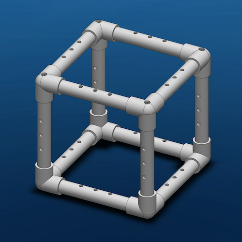
(Left) Perspective view. (Right) Top-down view.
The vessel carries a payload, shown in Fig.
Follow these instructions to investigate how to balance weight and buoyancy in a marine vessel:
- You have 8 corner joints (also known as a three-way joint) and 12 straight sections of PVC pipe, along with a mesh pouch and some zip ties
- Assemble your vessel so it looks like the sample marine vessel shown in ; your vessel may be shorter or taller than the vessel pictured here
- Talk with your partner and determine where you want to attach the payload (refer back to the hydrostatics videos if needed)
- Attach the payload to the vessel using zip-ties
- Weigh your vessel and payload; record this weight
- Determine the total underwater volume, $\nabla_{max}$, needed for the vessel to be neutrally buoyant (refer back to the section on buoyancy)
- Estimate how many ping pong balls are needed to get close to this volume. Take no more than 90 seconds on this! It's just a fast estimate; you'll revise this number based on experiential data shortly.
- Put this many ping pong balls into the mesh carrier provided
- Attach the mesh carrier to the vessel using zip-ties; refer back to the hydrostatics videos for guidance on the best place to attach your ping pong balls
- Put the vessel into a tank of water and note whether it floats to the water surface (too much buoyancy), sinks to the bottom (not enough buoyancy), or "hovers" somewhere in the water column (nearly neutrally buoyant)
- If there is too much buoyancy, remove one ping pong ball, put the vessel back into the water, and note what happens
- If there is not enough buoyancy, add one ping pong ball, put the vessel back into the water, and note what happens
- Repeat Step 10 until you reach a point where your marine vessel's buoyancy needs to change in a smaller amount than a single ping pong ball in order to achieve near neutrality for buoyancy.
- Brainstorm with your partner ways you could have adjustable buoyancy and/or make small changes to the buoyancy of your future ROV; record these ideas
- Remove your vessel and re-weigh the vessel including the mesh bag and ping pong balls
- Record this weight, the number of ping pong balls used, and whether you ended your experiment with your vessel floating or sinking
This experiment is preparation for how you will make your ROV nearly neutrally buoyant. Keep track of your notes for this lab so that you can complete the questions in the homework assignment.
ROV Demo (30 minutes)
Justin or your IA will show you a demo ROV. Observe the following things about this ROV and ask questions about:
- Where are the payload canisters? Why are they placed there?
- Where is the camera? Why is it placed there?
- Where are the thrusters? Why are they placed there?
- Where is the tether attached to the ROV frame? Why there?
- What does the controller look like? Why are the buttons and switches placed where they are?
- What does the inside of the controller look like? What are the main components? How are the buttons and switches connected to the electronic innards of the controller?
- How does the controller communicate to the ROV?
Keep track of your notes to these questions!
Next, your group will move to the test tank so that you can each drive the demo ROV around for 2-3 minutes. Use this time to observe the following about the ROV:
- Is the ROV easy to drive?
- Which directions are you able to drive in independently of the other directions (up, down, forward, backward, left, right)?
- Can you make the ROV yaw/pitch/roll?
- Do you like the arrangement of the controller?
- Do you think the thrusters are in a good location?
- What changes would you make to this ROV in a (hypothetical) second round of design?
Keep track of your notes to these questions!
Lab 2: Controls & Hydrodynamics
Checklist
| Before Lab | |
| During Lab | |
| After Lab |
Overview
In this lab, you will explore how your ROV will be controlled.
We’ll start with a soldering demo first, so that everyone can see how soldering is done and have a chance to ask questions. Then, you will work in groups of two to complete a soldering task so you can practice what you saw in the soldering demo. These groups of two can be of your choosing; this pairing is not relevant to your ROV team, you will all be split up into your actual teams later in the semester. If there is an odd number of students, only ONE lab group today may be a group of three.
After the soldering task, one half the lab will go do a thruster balancing experiment to learn about how the placement of thrusters impacts how an ROV moves through the water, and then move on to constructing a basic control circuit to gain some experience with our equipment. The other half of the lab will start with the control circuit exercise and the switch to the thruster balancing experiment.
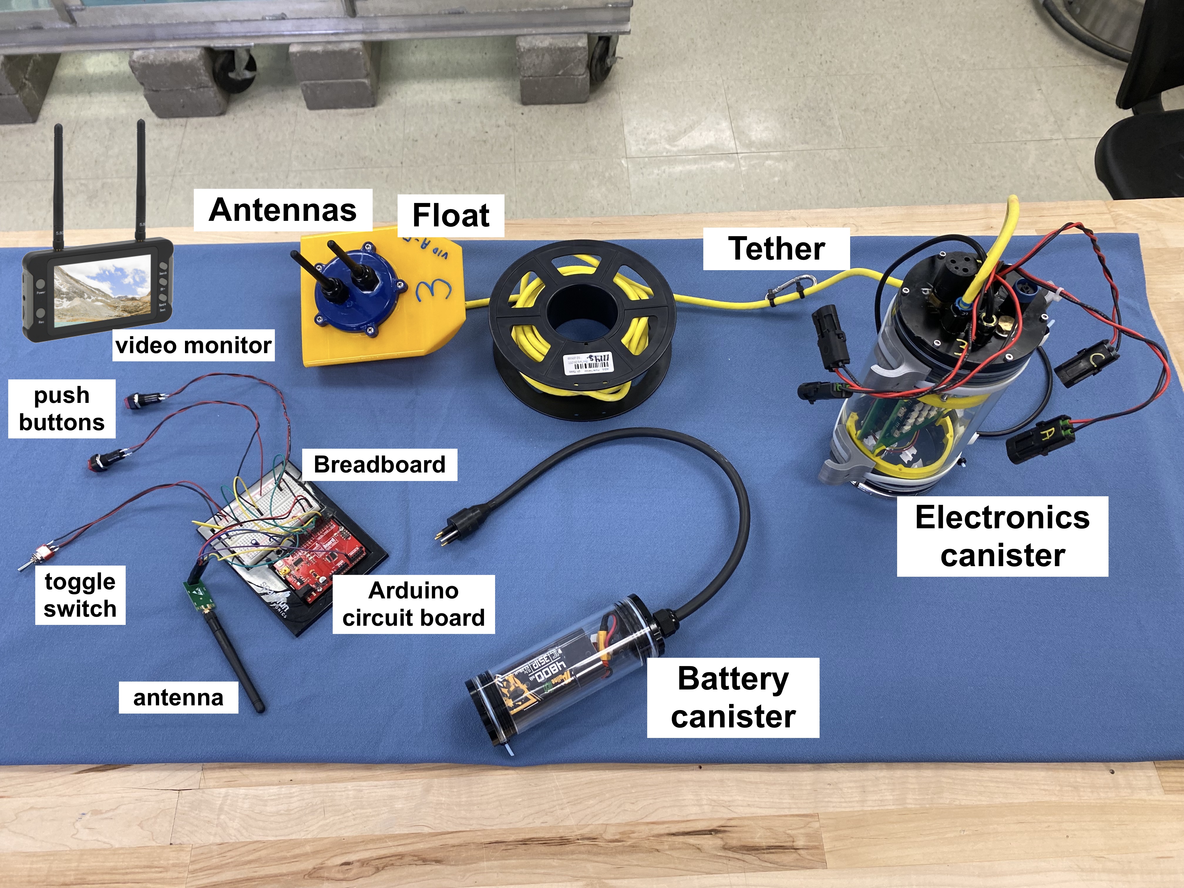
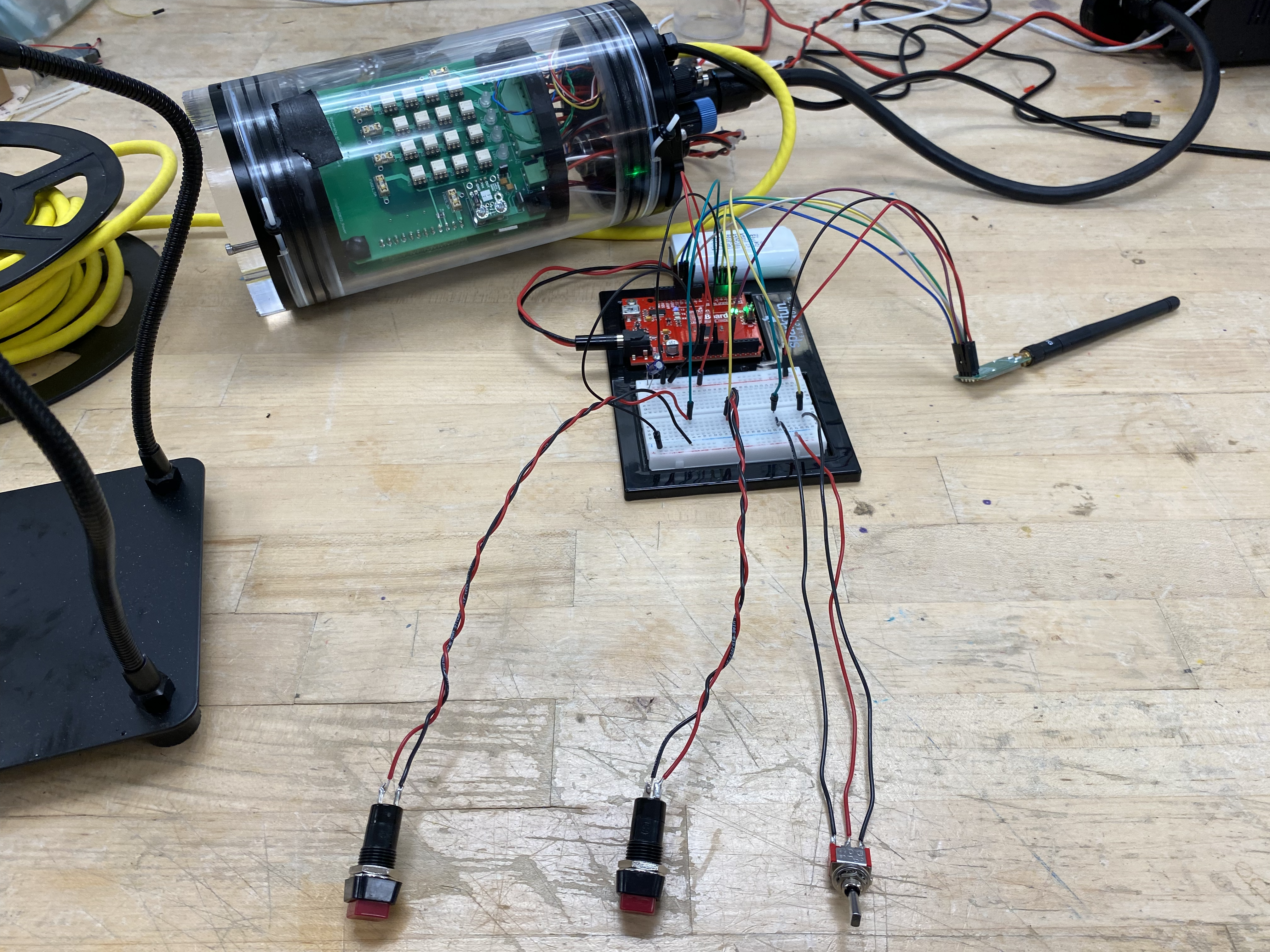
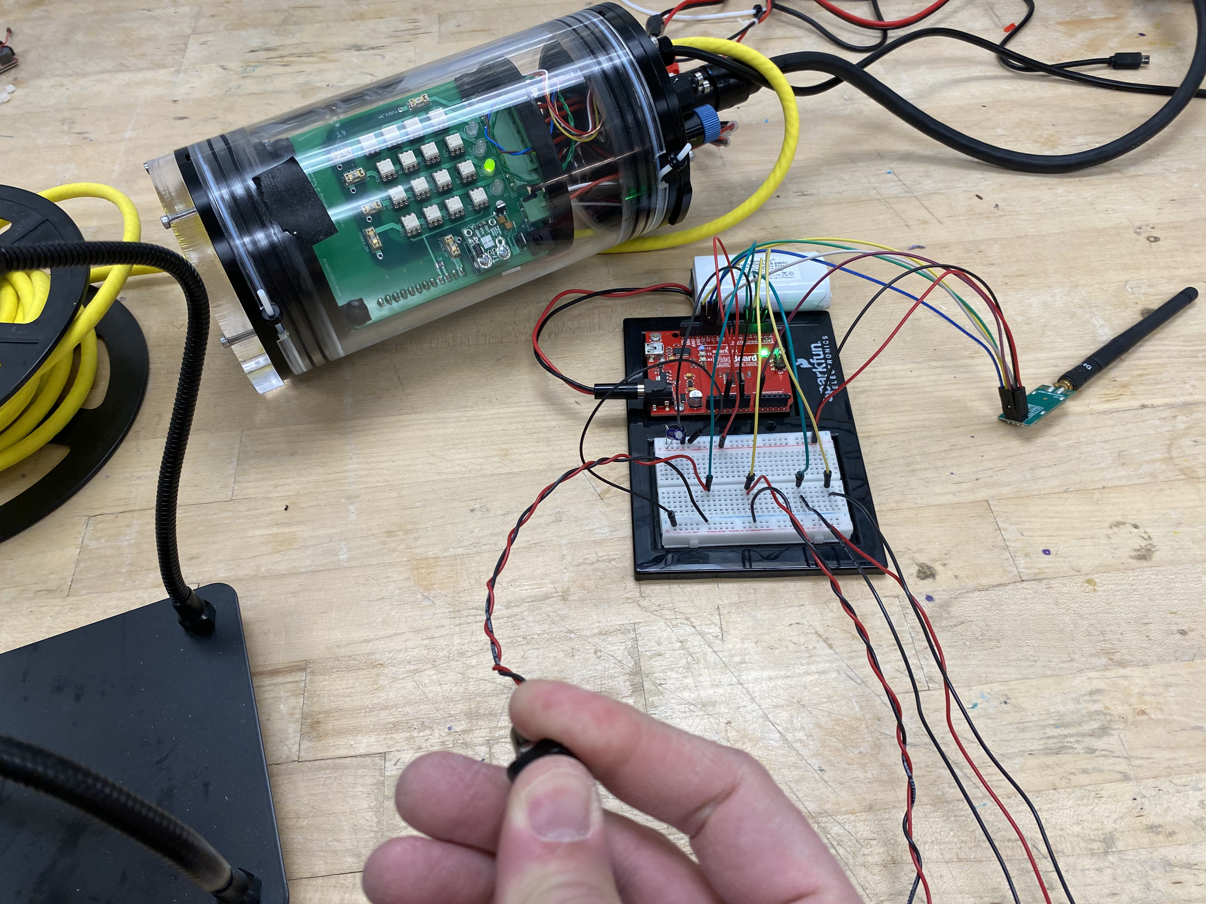
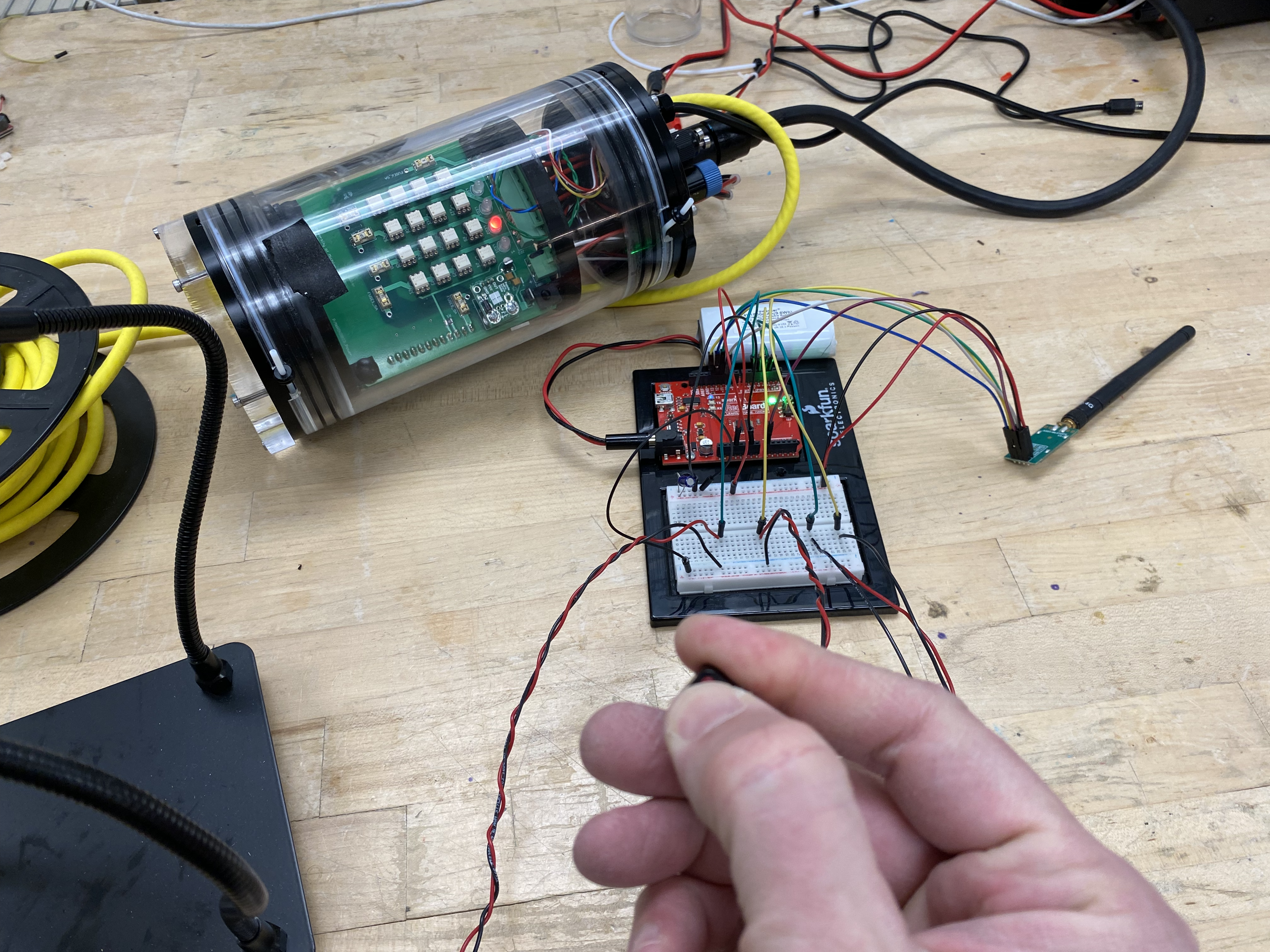
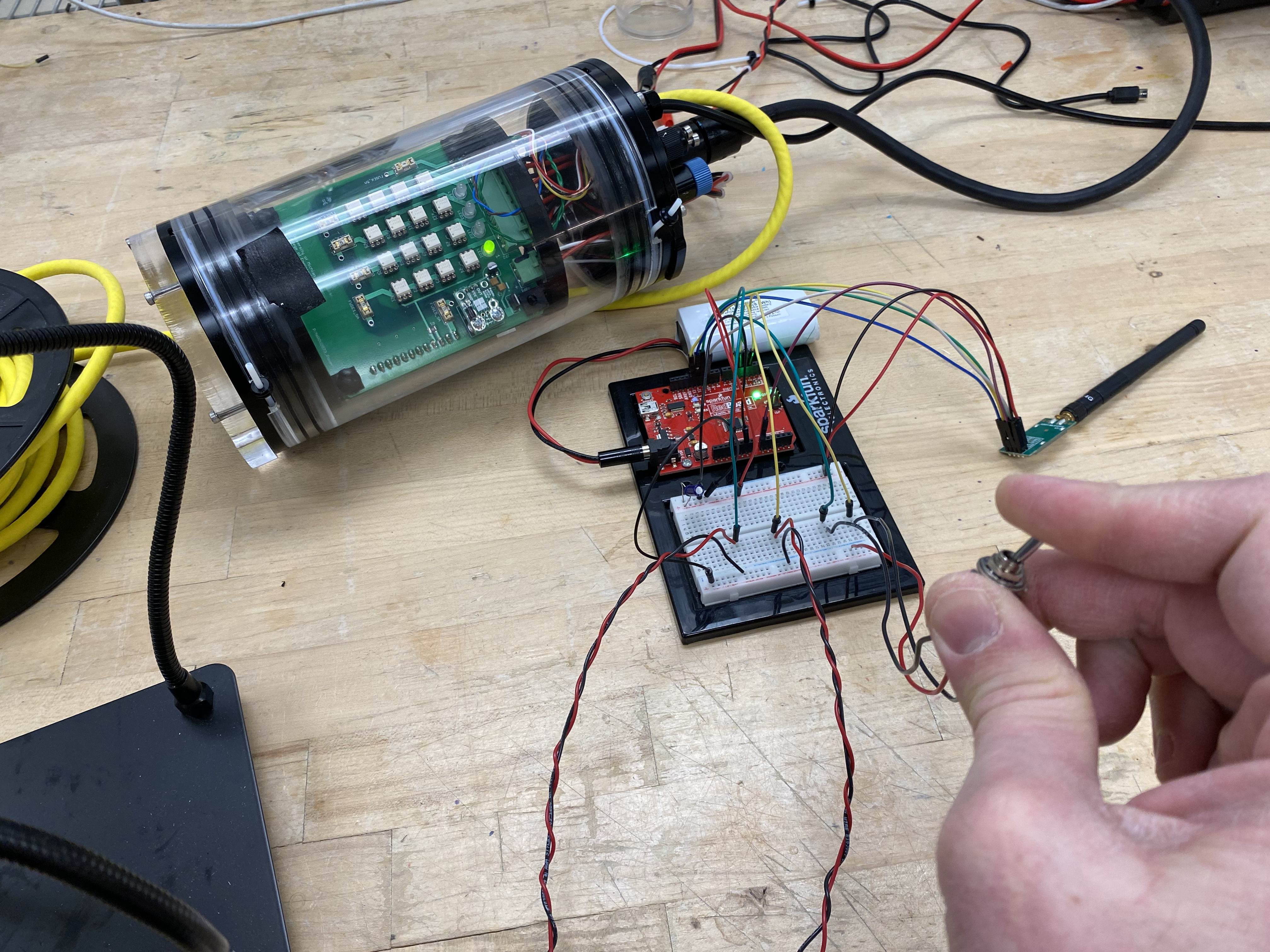
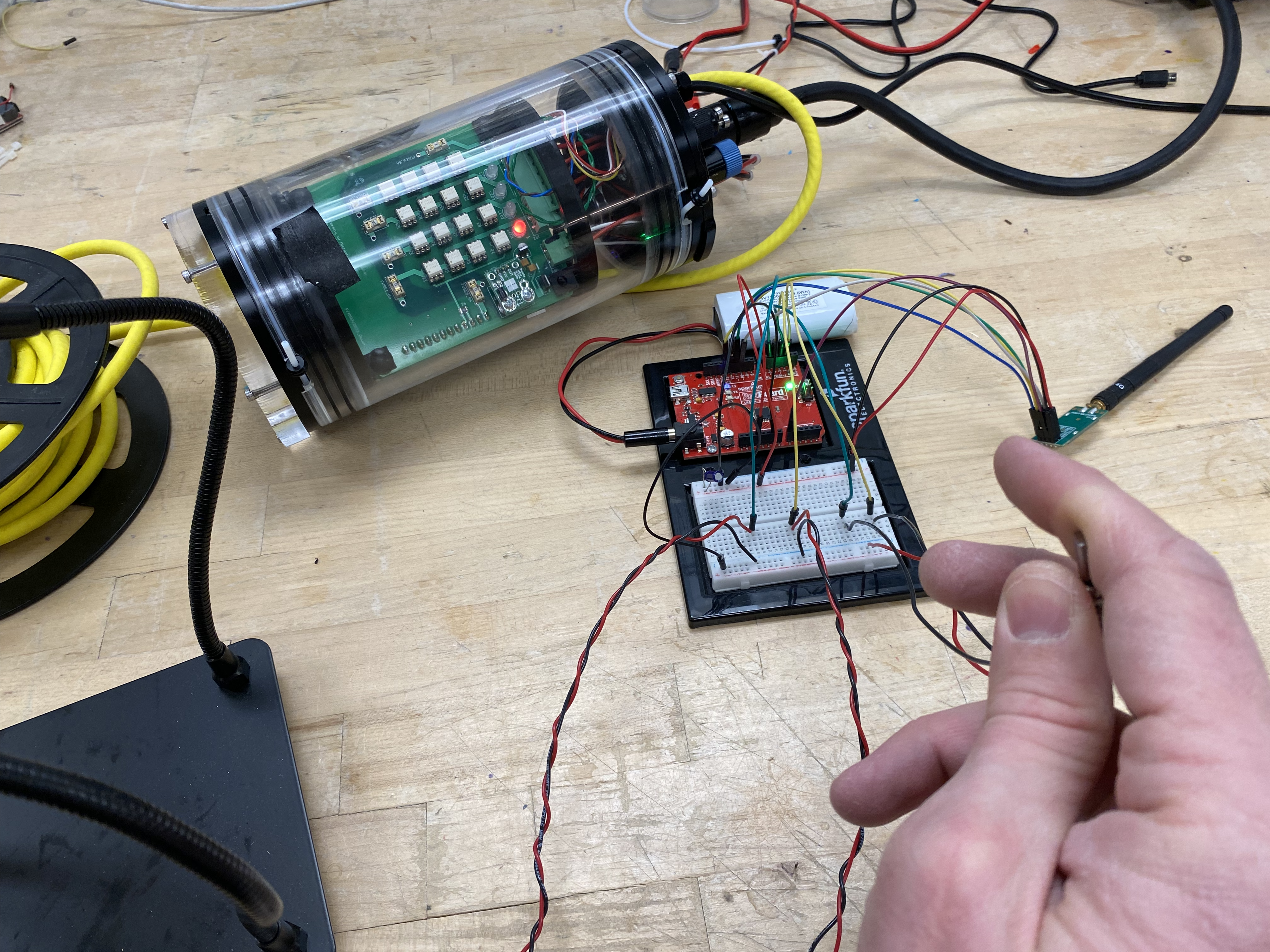
The ROV payload system is shown in Fig. The payload itself is the clear plastic cylinder with the electronics inside. A yellow, neutrally buoyant tether connects the payload to a blue and yellow float with black antennas at the top. This float stays at the surface of the water to transmit and receive wireless signals from your controller. Your controller will have buttons and/or switches (seen in the lower left of this picture) that are wired into a breadboard/Arduino circuit board system. The Arduino has its own antenna with which it transmits and receives data from the float.
The control circuit exercise will provide you with an opportunity to familiarize yourself with some of the skills required to build your control console, such as soldering, and it will provide you with an introduction to how the control system works. You will solder wires onto two push button switches and one toggle switch and connect those switches into a breadboard (prototyping circuit board) connected to an Arduino and an nRF24L01 transceiver (here’s a link about wireless communication with nRF24L01 transceivers if you want to learn more). You will demonstrate the operation of a radio link that transmits switch position information to a receiving ROV payload, lighting up LEDs and operating a thruster.
Reminder from the Before Lab Checklist! You must read the section on the ROV’s Control System before you come to lab so that you are familiar with the components and terminology that you will be using in today’s lab.
Soldering Demo (10 minutes)
Justin will demonstrate basic soldering techniques that you will use in your soldering task today. You will be soldering in this lab, so pay attention to what he does and make sure to ask questions!
Soldering Task (20 minutes)
In groups of two (we have ten soldering stations) you will each practice soldering the different joints that were demonstrated at the beginning of class. Each student must complete the three example joints on their own and the work should be tidy and sound. Show your work to the IA or lab manager when you are done.
Try to balance being goal-oriented here without stressing out about it. You do need to be able to produce quality solder joints for this class and probably other classes you will take at U-M, but you are not expected to do it perfectly on your first try. Soldering is not super hard, but it is a skill and takes some practice to get your hands steady and your technique right.
Some solder contains lead, which is toxic if ingested. If you work with lead solder, wash your hands before eating. The solder you will use in this lab is lead-free.
Use the pictures below to guide your soldering practice.
Example Joint #1: Solid Core Wire
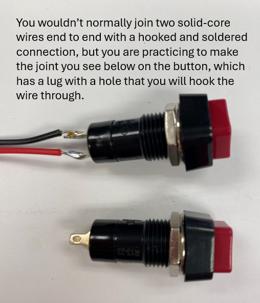
For your ROV controller, you will be connecting buttons and switches to solid core wire. You will make this connection by first stripping a small part of the insulation away from the end of a wire and then making a small hook to put through the hole on the lug (the metal part that sticks out of the bottom of the button/switch). You would then pinch the hook closed and solder the joint, resulting in a strong connection like that shown in Fig.
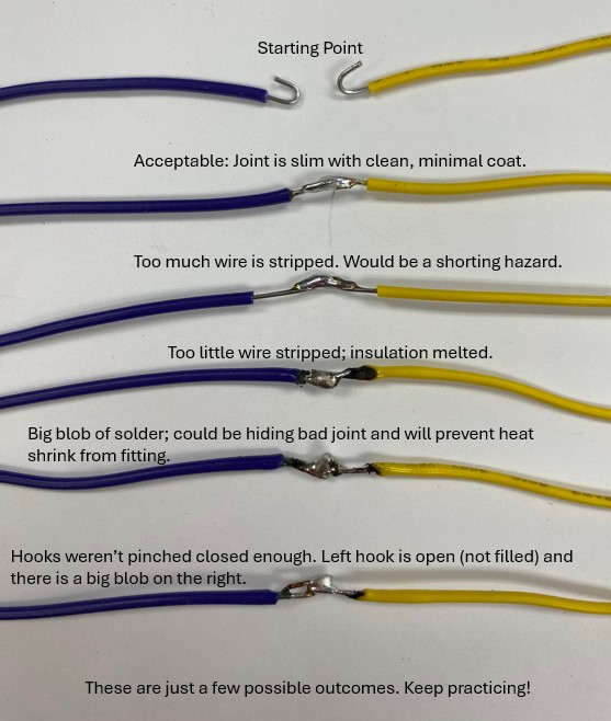
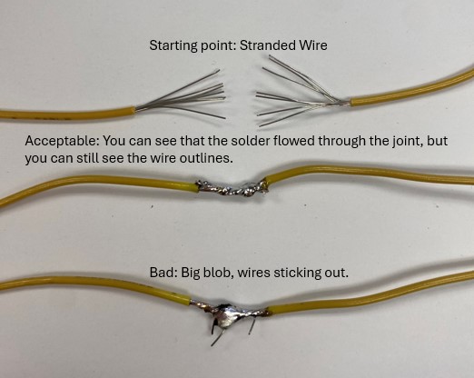
Before you start trying to wire buttons and switches, practice your soldering skills by soldering two solid core wires to each other. Fig shows your starting point with the two wires and the joint that you are aiming to create, along with some common pitfalls to watch out for when soldering.
Example Joint #2: Stranded Wire
You may also need to use stranded wire to create a connection in your ROV control circuit. Practice creating a joint between stranded wires by twisting the bare ends of the wire together and then applying just enough solder to fill in the gaps around the small wires and smooth out the joint, as show in Fig.
Example Joint #3: Wire to Perforated Board (Perf Board)
The last type of joint that you need to know how to make is how to connect a wire to a perf board, which is an electronics board that is perforated with small holes. Fig shows a perf board with a “practice component” that is just a small length of wire.
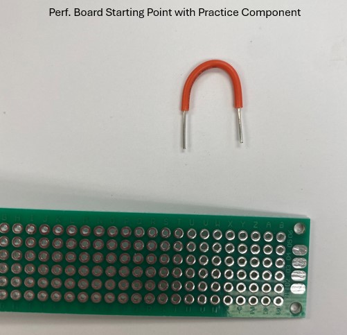
Practice creating a joint between a wire and a perf board using this practice component. First clip your perf board onto the small vise to hold it steady. Then push the bare ends of the practice component wire through holes in the perf board. Push the ends of the wire through the “back side” of the perf board (the side that does not have the little metal circle around the hole). Then, use the soldering iron to heat up both the wire and the little metal circle before applying solder; review the how to solder video if you need to. After you are done, trim off any excess wire sticking out, as show in Fig.
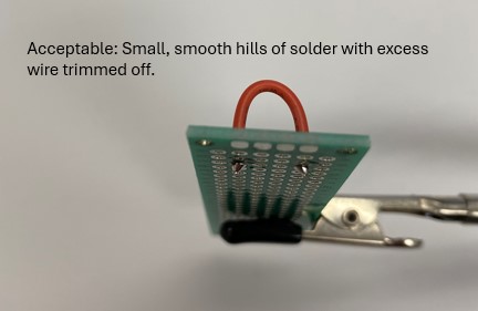
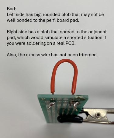
Fig shows some common mistakes when soldering joints on a perf board.
Remember to show your work to your IA or lab manager when you are done!
ROV Thruster Moment Balancing (20 minutes)
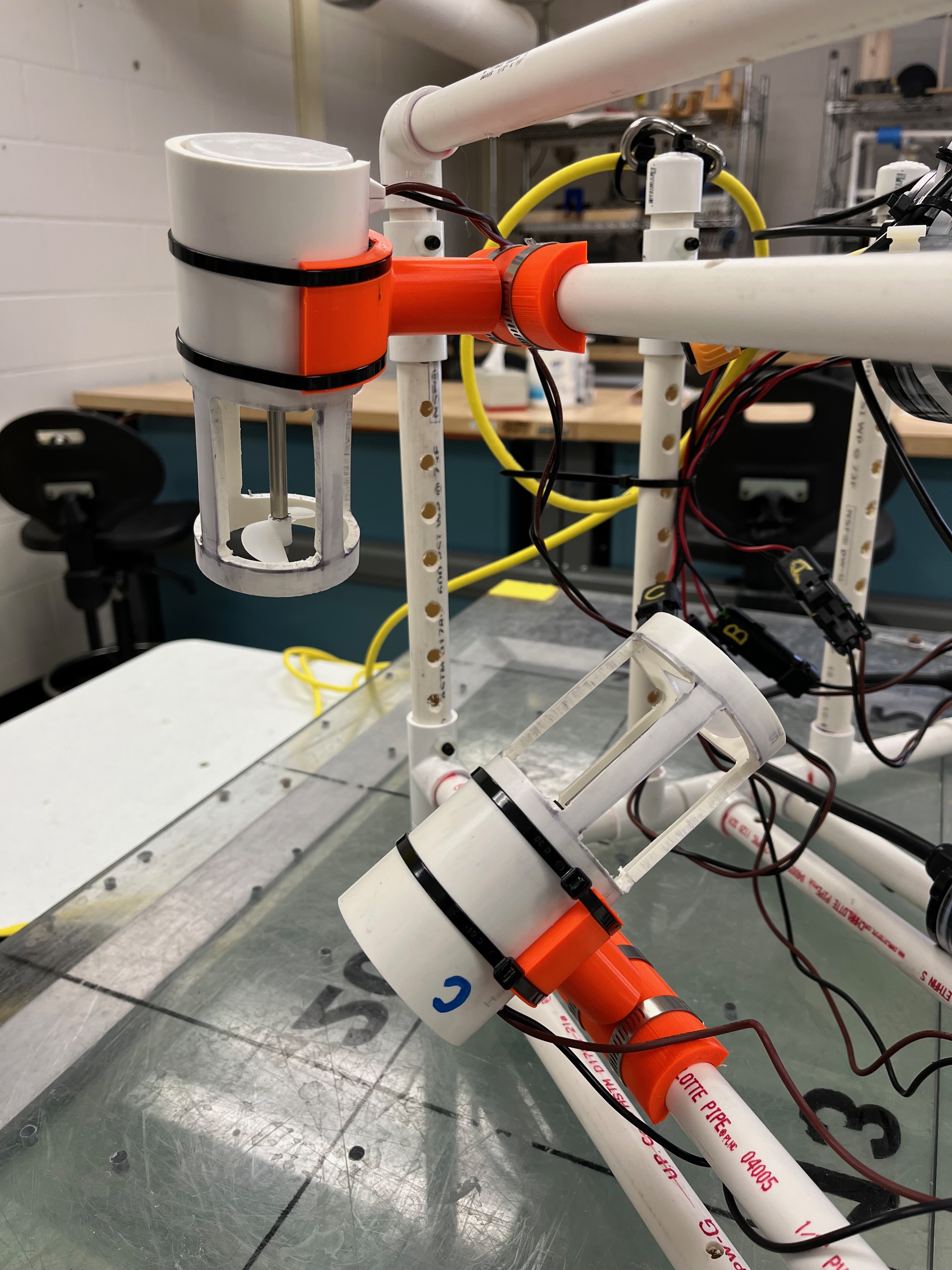
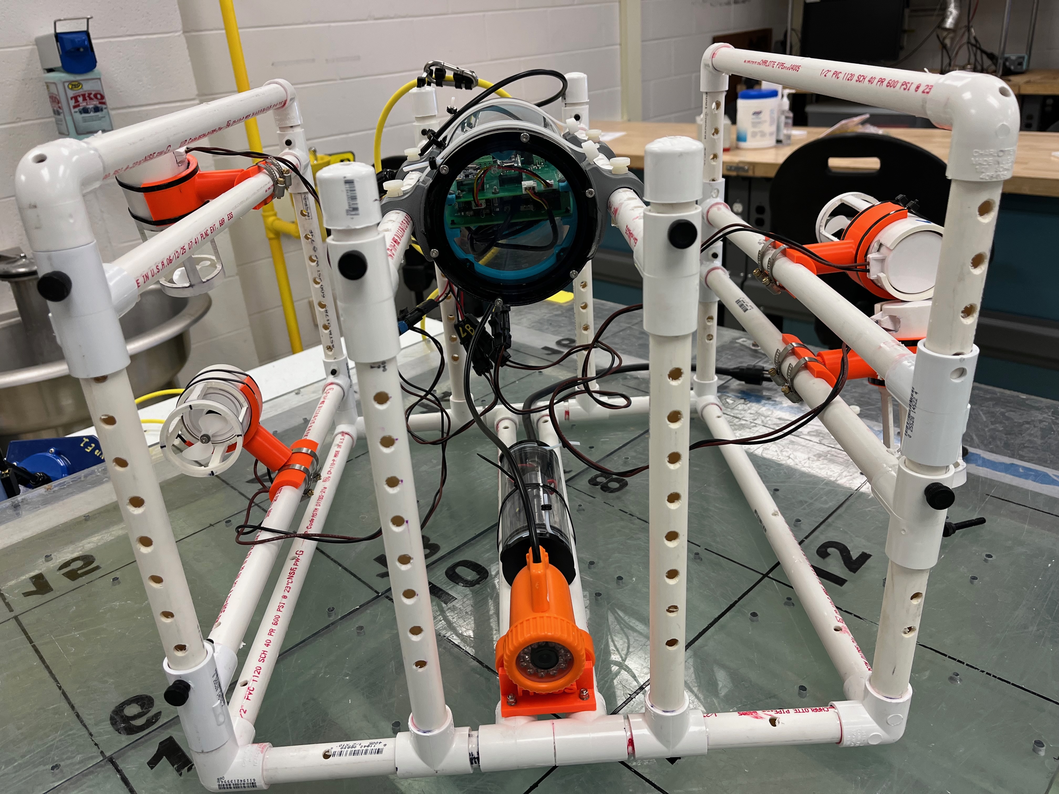
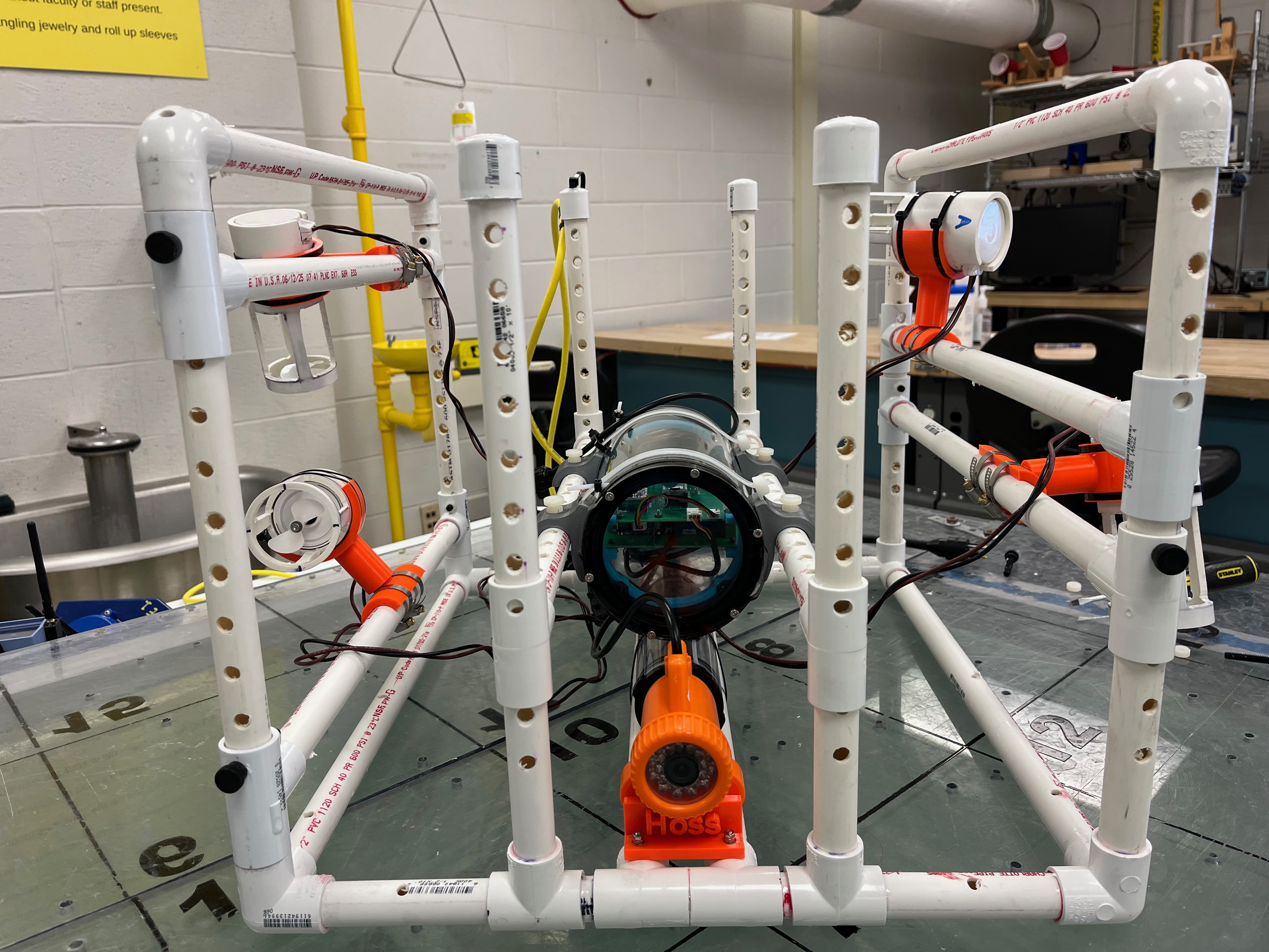
Your ROV has the ability to use up to four thrusters and you can place the payload canisters wherever you want to on your ROV. But this means you have a lot of potential locations to explore for your ROV components! Justin has created an adjustable ROV (Fig) for you to experiment with so you can place components in different locations and see how that affects the ROV’s action in the water.
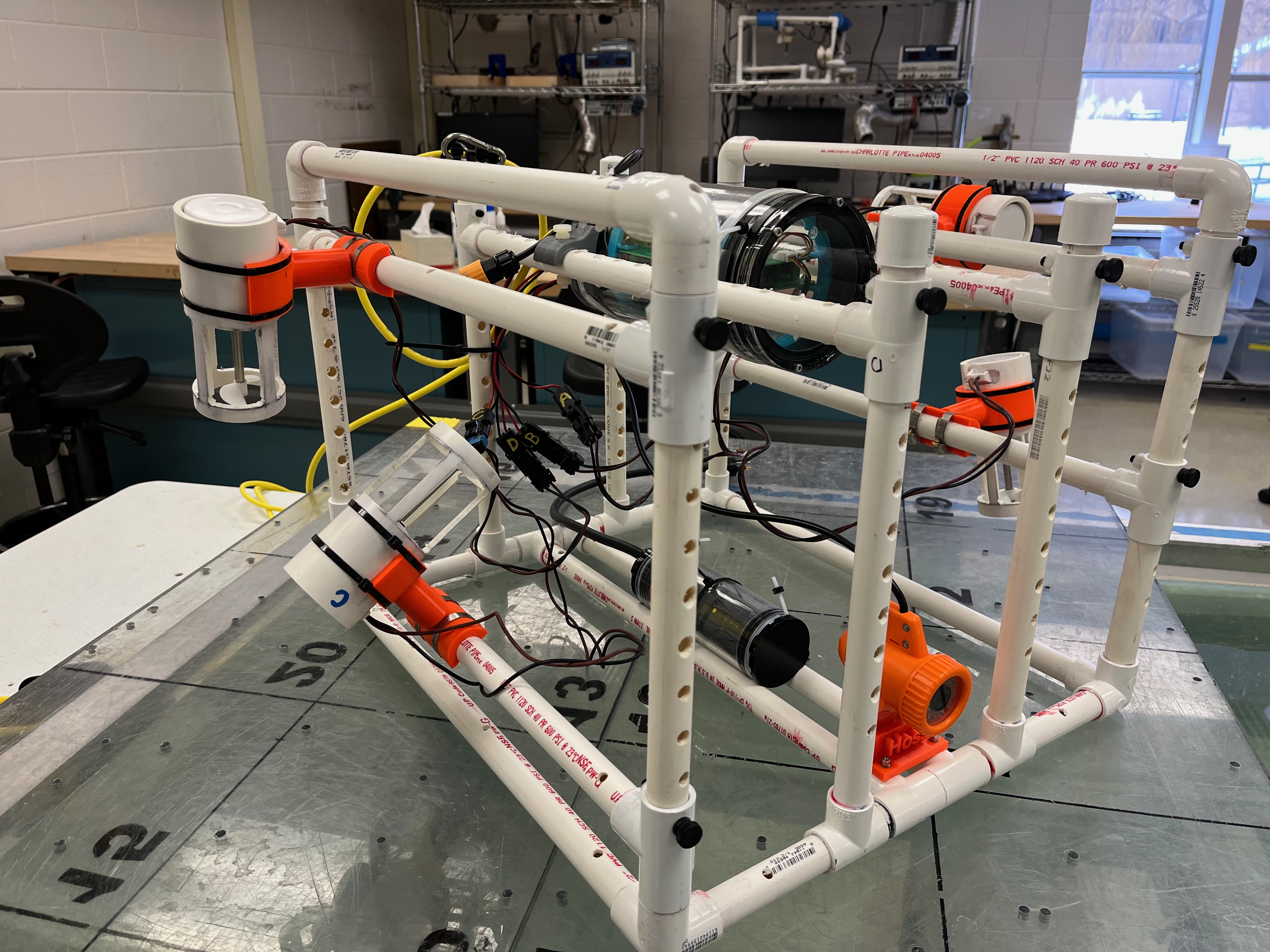
The ROV you will use in this lab has many ways to adjust ROV components. The thrusters can be pulled off and repositioned to try different angles; you can also use a screwdriver to loosen the hose clamps and reposition the thrusters to be inside or outside the ROV frame (Fig).
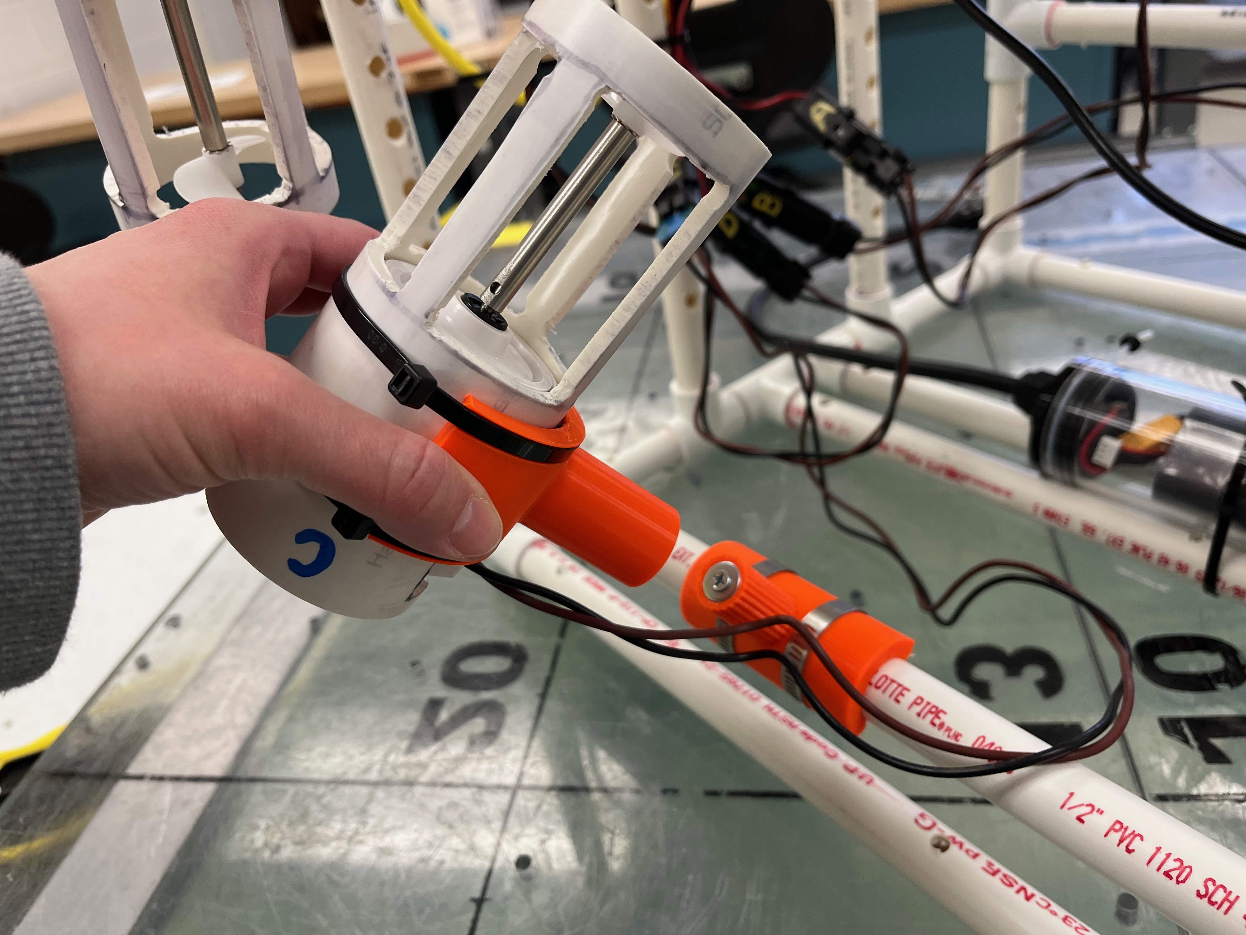
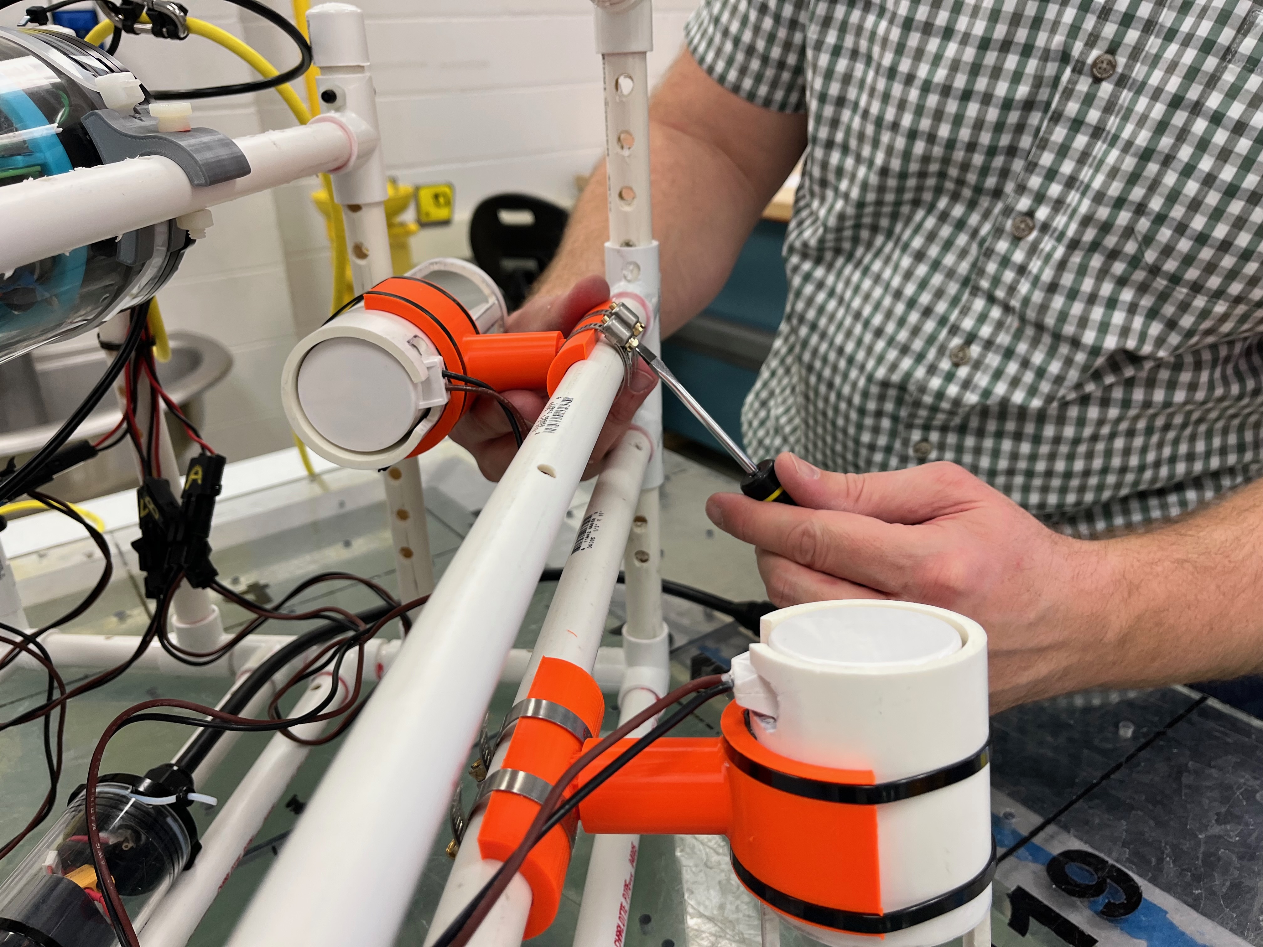
You can remove the nylon bolts (Fig) and adjust various parts of the frame by sliding the part of the frame and then re-inserting the bolts .
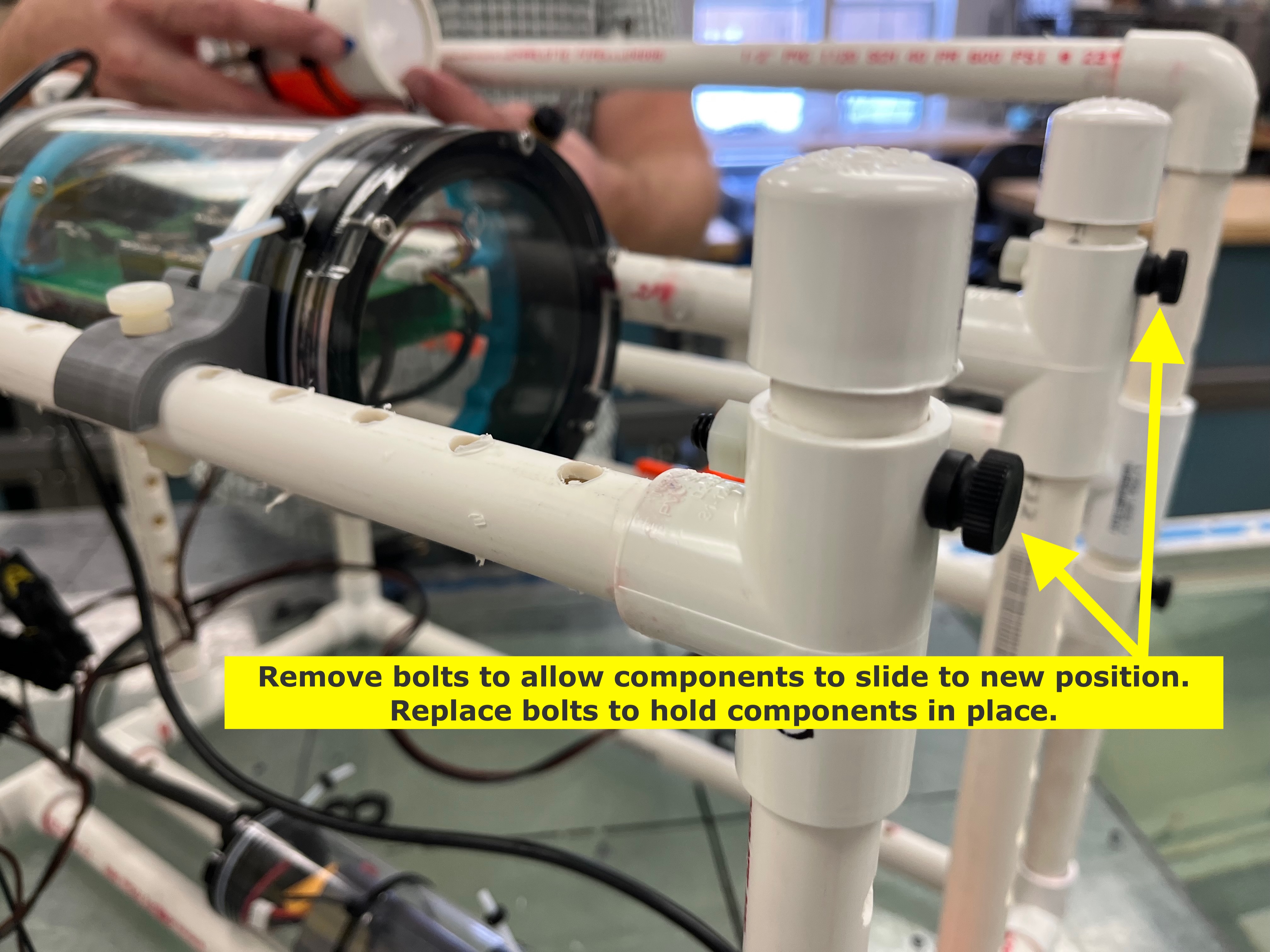
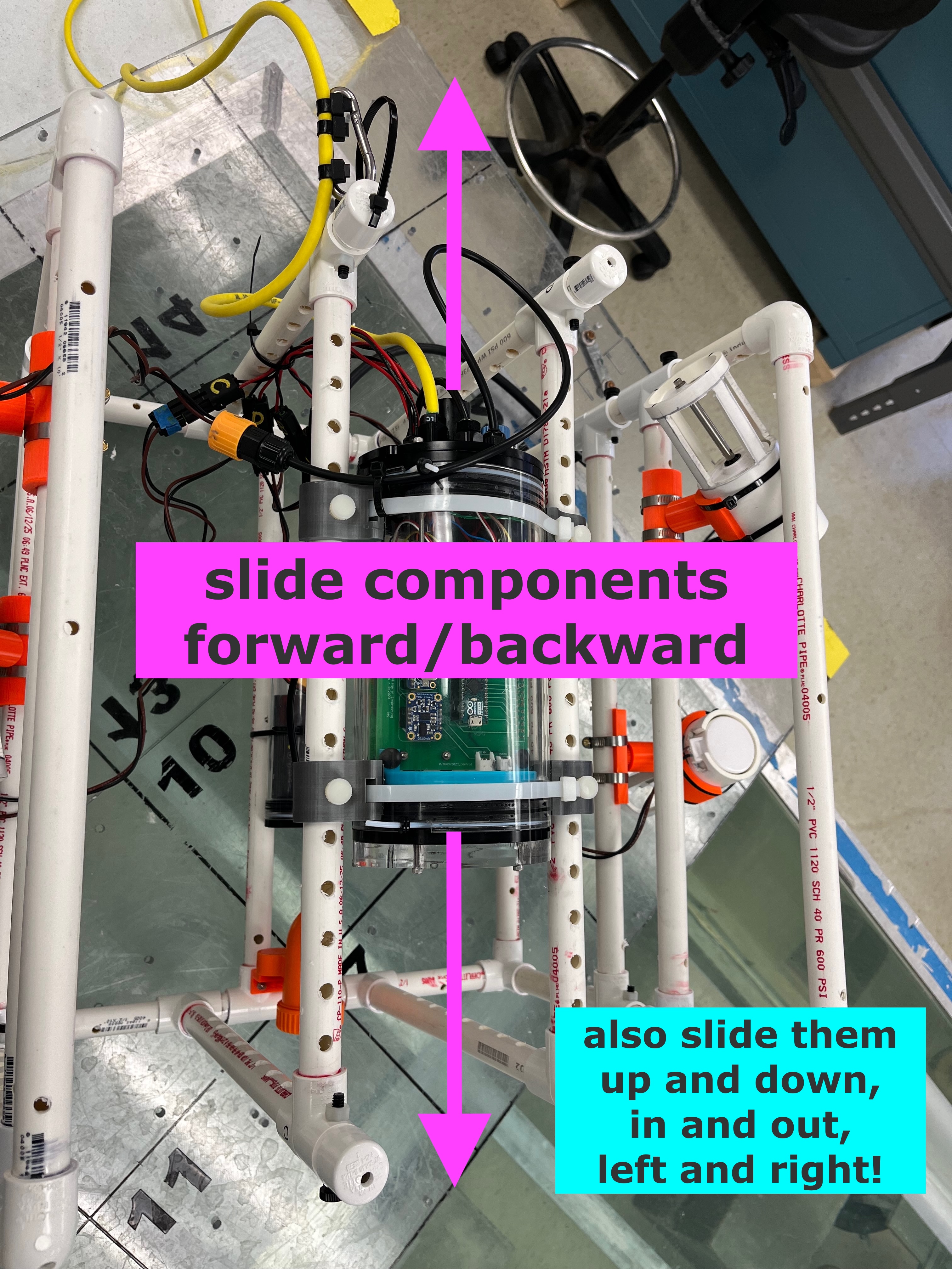
For example, you can adjust the ROV to have the electronics canister be both higher and lower within the ROV frame (Fig) and then drive the ROV around to see if that changes how the ROV drives.
In general, you can move around just about anything on this ROV during lab. Don’t forget to move things forward and backward (“fore/aft”) to see how that changes the ROV’s motion, too!
During the lab, you will be called over by your IA to perform the following experiments using the demo ROV:
- Determine how to position the thrusters such that the ROV does not pitch up or down when it travels forward
- Measure and then compare the rates of yaw when the side thrusters are inside the frame vs. when they are outside the frame
- Compare the vertical maneuverability of the ROV when the ROV can move purely in heave vs. when the ROV must pitch upwards/downwards to move vertically
- Measure and compare the rate of vertical ascent and descent with the vertical thrusters pointing up vs. when they are pointing down
- Move the electronics payload to different locations and observe how that affects the ROV’s motion through the water.
- Any other combinations/locations you want to explore!
Take notes on these experiments. You will need them to answer questions on the assignment for this lab and to refer back to when designing your own ROV.
Basic Control Circuit (60 minutes)
You will work in teams of two to construct and test the two switch options you will have available for the ROV project. One is a simple toggle button (recall this is a single-pole-single-throw switch) that turns the circuit either “on” or “off”. The second is a single-pole-double-throw toggle switch. A switch “terminal” or “lug” is the little post that sticks out of the bottom of the switch; you attach wires to the terminals to create a circuit.
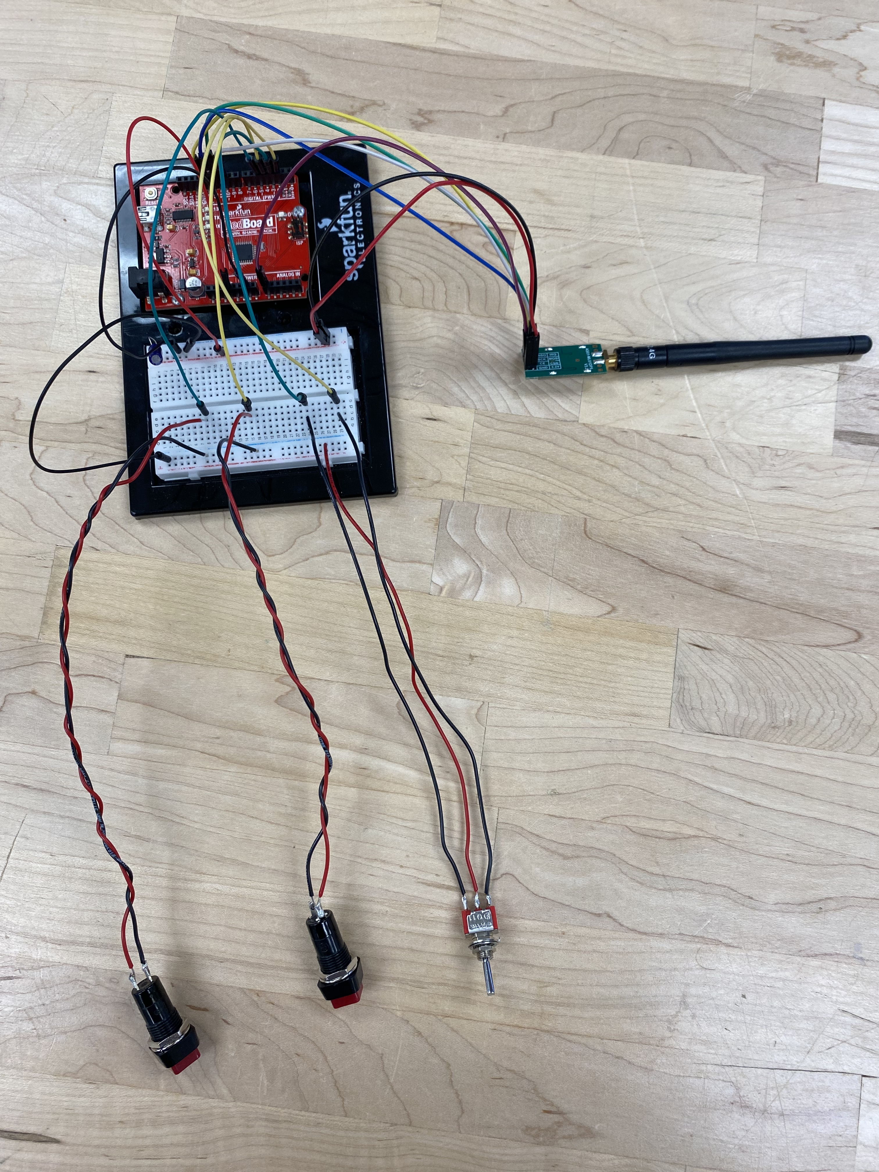
Once you have obtained one switch and two buttons, you will connect the switch and buttons to a breadboard, and then connect the breadboard to the Arduino circuit board. You will then use a nRF24L01 transceiver to wirelessly transmit to an ROV payload to verify that your circuit is complete and functioning correctly. A completed basic control circuit with the ROV payload is shown in Fig. You can use this figure to help guide you through this exercise, but stop and ask Justin or your IA questions whenever you are unsure of what to do! This lab is all about learning as you go! 😊
The BreadBoard
Recall from the section on the ROV’s Control System that breadboards (also shown in Fig alongside an Arduino board) are simple tools used in circuit prototyping that allows you to quickly and easily change your circuit without the need for soldering.
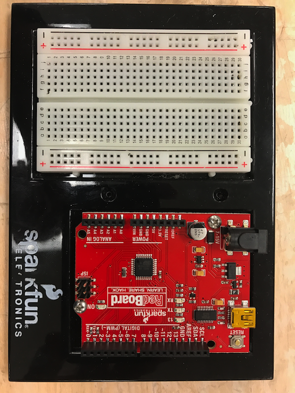
For the ROV project, you will be given an Arduino breakout board with screw terminals to complete your control circuits. This is your opportunity to experiment with the breadboard and understand how it works. Your IA and Justin will give an overview of the breadboard in the lab.
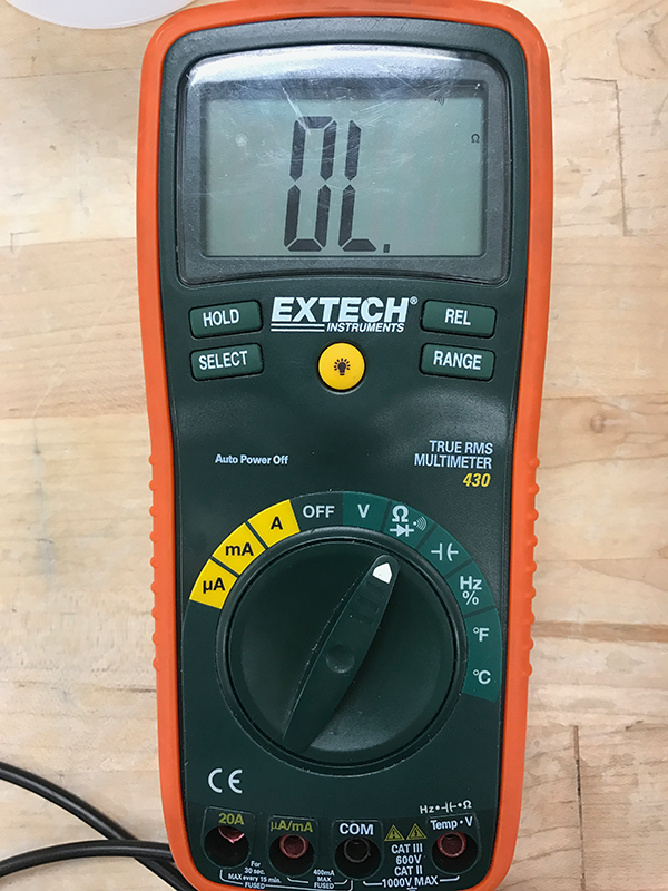
Take some time to experiment with an ohm-meter and discover where continuity lies within the board. To do so, turn the meter to the ohm position (Fig) and press the select button until a sound icon appears on the screen.
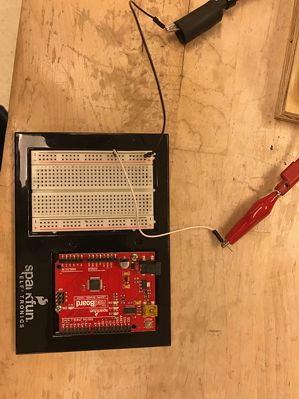
When the leads make contact you should hear an audible sound. Additionally, use several of the supplied jump wires to test out various configurations on the bread board and discover how to get continuity between circuits (Fig).
If the previous sentences make no sense to you, that’s okay! Ask lots of questions in lab, and Justin and your IA will explain everything.
Wiring the Arduino
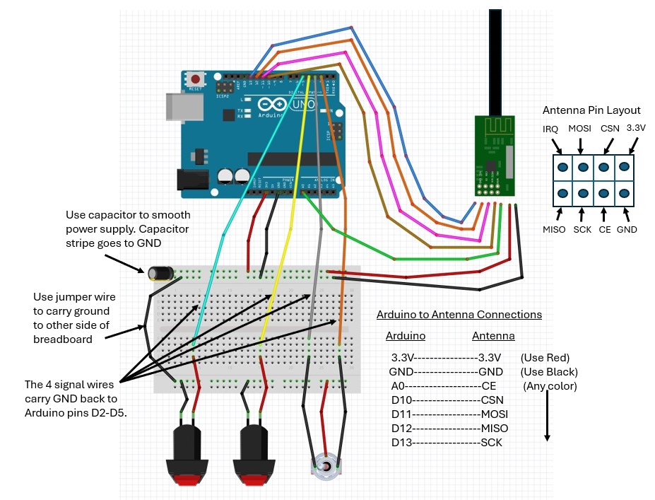
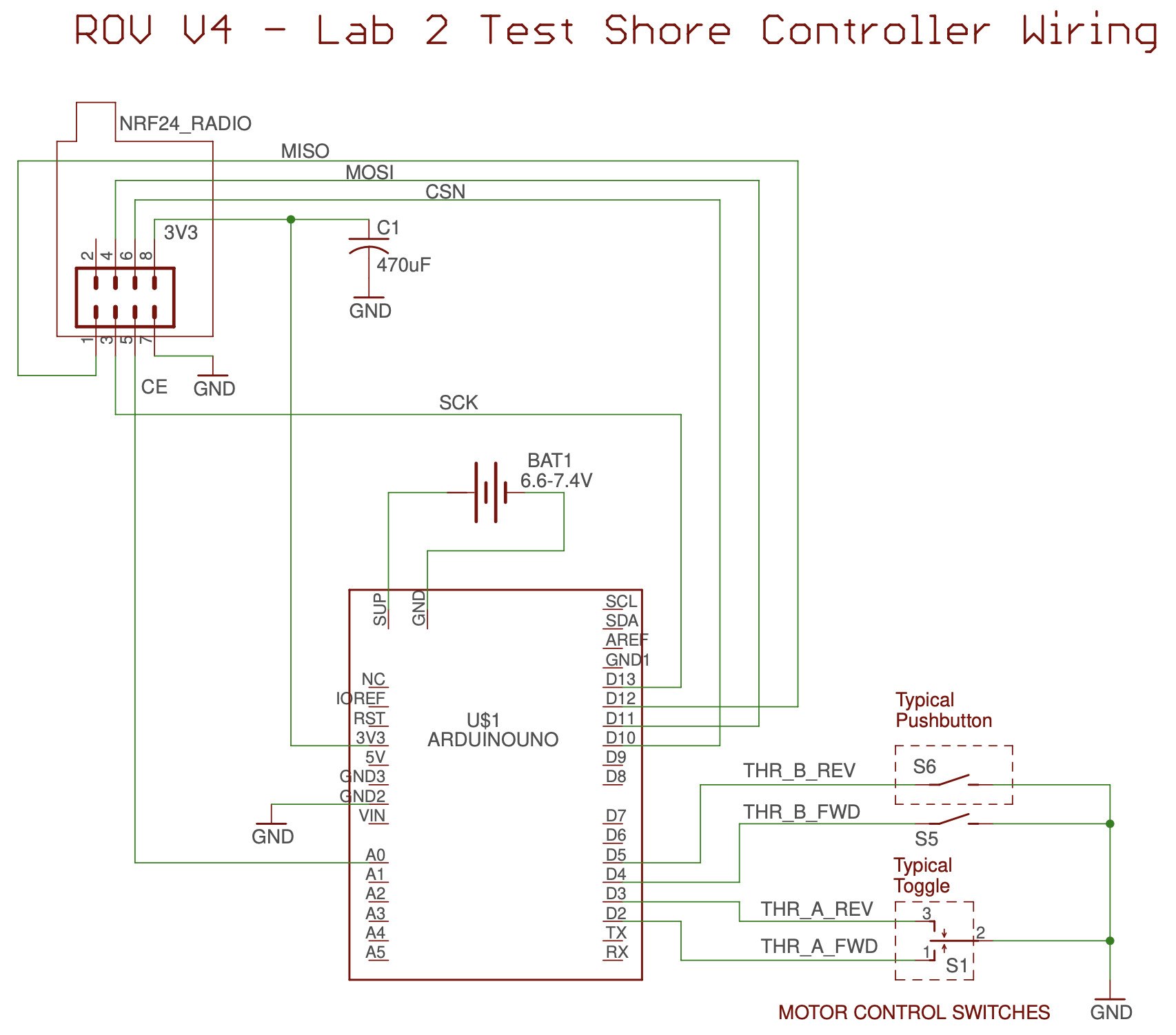
- Using either the sample on the display table OR the picture of the completed Arduino and breadboard shown in OR the wiring guide shown in OR the schematic shown in (if you have more electronics experience) as a guide, make the connections on the Arduino and breadboard. The jumpers will insert into the holes of the breadboard and/or the headers on the Arduino.
- Important!! Both the breadboard and the Arduino may be mounted on your unit base in either direction. If yours does not match the sample or the figure you will have to figure out how to wire it in the orientation it happens to be in.
- Don’t bother counting holes to match the picture to your breadboard. The breadboard contains banks of identical rows that are there to be convenient for you. All that matters is that you make the wire-to-wire and wire-to-terminal connections on your components correctly.
ASK QUESTIONS if you are interested in understanding more about the circuit!
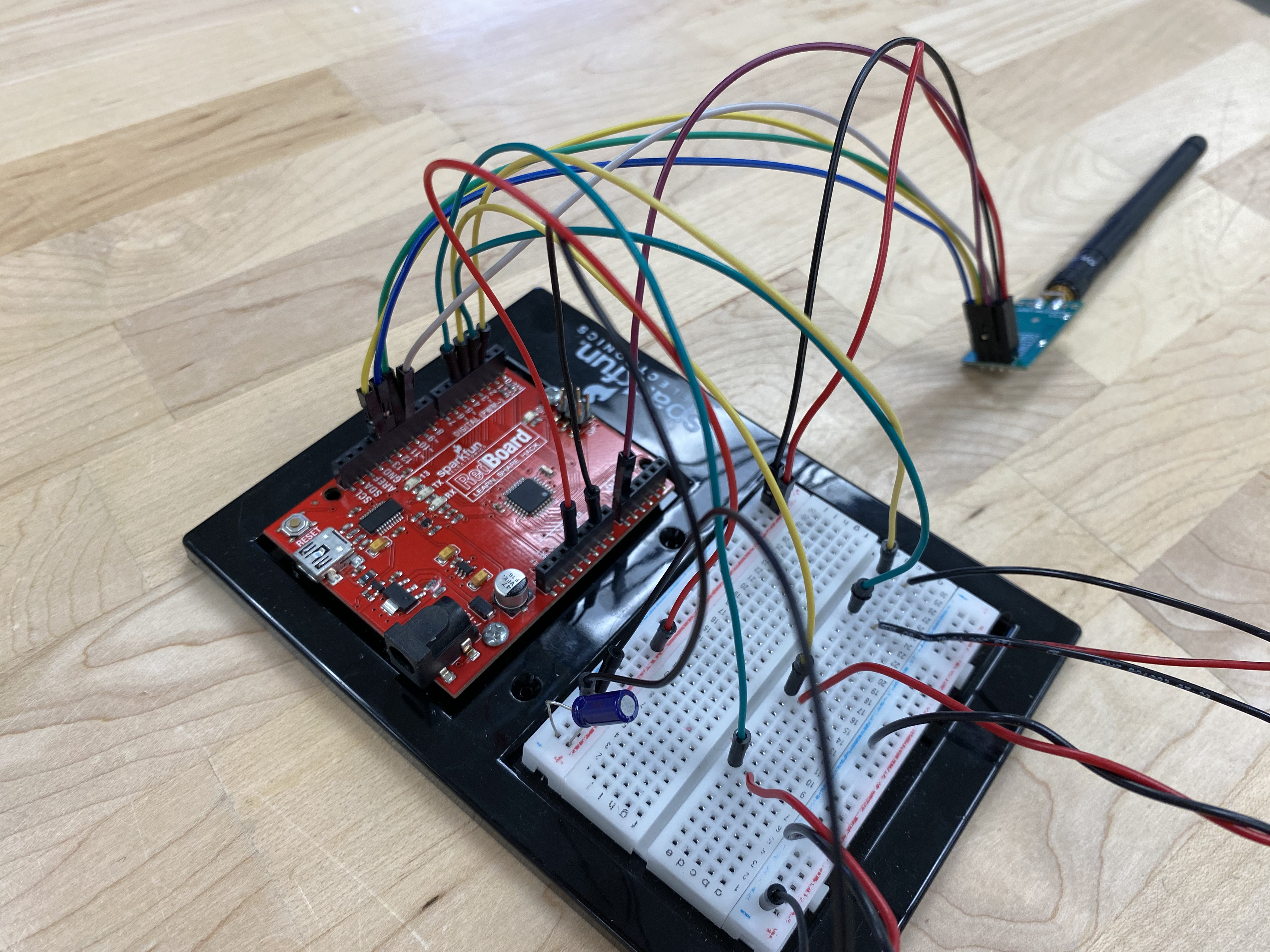
When you are all done, your test circuit should look like what is shown in Fig.
Testing the Circuit
- When you think your Arduino is ready to be tested, bring it to the instructor and have the control program loaded into it.
- Connect a 7.2V battery to your board.
- Operate your push-buttons and toggle switch and verify that the ROV payload responds correctly through the radio link (see Fig for the buttons and Fig for the toggle).
Cleanup
- Unwire your Arduino and leave it at your workstation.
- Discard cut wire.
- Clean up wire stripping residue.
- Make sure your soldering station is shut down.
- There shouldn’t be any little chunks of wire or plastic on your workbench after cleanup. Leave the station clean for the next team please.
Lab 3: 3D Modeling
Checklist
| Before Lab | |
| During Lab | |
| After Lab |
Overview
Computer Aided Design (CAD) is an incredibly powerful tool available to the modern engineer. It allows for precise, accurate, and detailed models of both large- and small-scale engineering projects. Once we have a model of a design, we can do many powerful things with it. Most minds would go straight to 3D printing, where we can turn this model into something physical, allowing us to see its scale, weak points, and if it serves the need it is designed for. In addition, we can use a model to measure the amount of material needed, as well as certain properties such as the center of mass or center of buoyancy (part of today’s task). Other uses may be to run finite element analysis to discover the structural strength, or computational fluid dynamics to estimate the resistance and flow around your object.
Clearly, CAD is beginning to revolutionize how we undertake engineering projects, and as a new generation of engineers going through school now, you are in a position to make great contributions to engineering projects directly out of school if you get a solid understanding of how CAD works now.
During the course of this lab, you will create a box like frame with a Payload for an ROV (Fig) to practice creating a 3D model with the OnShape CAD program.
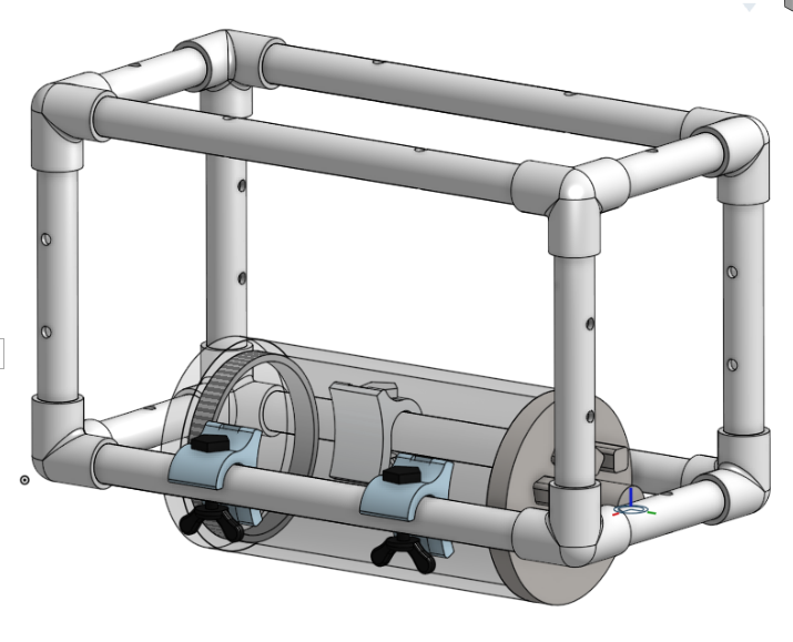
Working with a partners, you will learn how to mate pieces together to make an assembly. Once complete, you will save renderings of this model as directed to turn in for homework. Then, you will proceed to making your own model of a PVC structure for next week’s lab.
How Partners Will Work With This Lab
In this lab, there are two roles: driver and navigator. The driver is the person following the lab instructions and working directly in Onshape. The navigator is following the lab instructions and watching what the driver is doing to make sure they don’t accidentally make any mistakes. There are a lot of steps in these lab instructions and two sets of eyes on the model are better than one set of eyes!
You and your partner will share your documents with each other and then trade roles back and forth throughout the lab so that each person gets a chance to work in Onshape and help guide the collaboration. This is how we hope you will do your 3D modeling on your ROV team!
If/when you get stuck during this tutorial, PLEASE ask your IA for help!
Log in to Our Class in Onshape
Log in to the CAEN machine at your lab station. Then, go to Onshape and sign in with the account you already made using your U-M email address.
You must be logged into Onshape with your U-M account in order to access the materials you need for this lab.
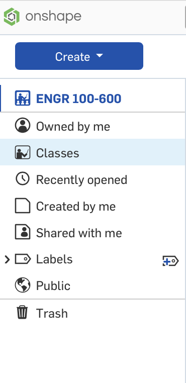
In the left-hand side bar, you should see ENGR 100-600 at the top. Don’t click here! Instead, click on Classes:
You should now see our semester-specific class:
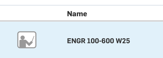
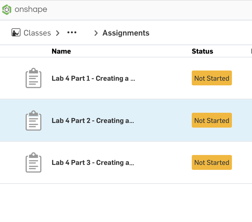
Click the class that is your current semester. That will take you to the list of assignments for this lab:
Reminders on How to Navigate in Onshape
It takes some practice to learn how to navigate any CAD program. Onshape has an excellent chart explaining how to navigate in the program, move parts, change the camera view, etc. We do recommend using a mouse when working in Onshape, but if you don’t have one handy, here are some friendly Onshape navigation tricks for trackpad users:
-
You are presented with the three coordinate planes. Recall, you will be sketching on these planes (and others, if you choose to define them).
-
At the intersection of all three planes is the origin.
-
Single clicking any object will select it. A single click and drag will open a selection window
-
A solid border, obtained by clicking and dragging leftwards, will select all objects that are completely enclosed in the selection window
-
A dashed border, obtained by clicking and dragging rightwards, will select all objects that the selection window touches
-
Clicking and dragging with two fingers will rotate the model to your desired orientation. This is useful when you are trying to get a sense of what you have created, and to admire your model from all angles.
-
Clicking on a face, edge, or corner of the cube at the top right of the screen will rotate the model to the selected view. This is useful if you need a precise, planar view or a view from an exact angle. You can also use the arrows around the cube to rotate it by a small amount in the direction you select.
-
Dragging up or down with two fingers will zoom in and out. This is useful for when you are working on parts of your model, and do not need to see the entire object, or once you have finished a specific part, observing how the whole model looks.
-
CTRL + two finger click-and-drag will allow you to pan, in case the model is out of view.
-
CTRL + Z (Windows) or ⌘ + Z (Mac) will undo your last action.
-
If you get lost, click on any face of the cube in the top right and you will be transported back to the origin at the center of your screen.
Part 1: Creating a Part from a Sketch
3D CAD programs typically work by turning closed 2D curves made in a plane you define (sketches) into 3D by either extruding the sketch linearly, or revolving the sketch about an axis to create a solid. Let’s practice this by creating a PVC pipe with holes in it.
| Step | Directions | Walkthrough |
| 1 |
In your partnership, choose who will start as the driver; the other partner will start as the navigator. It doesn't really matter who starts with which role: you will be swapping back and forth every 15 minutes or so when your IA tells you to swap roles.
The partner who is currently "driving" should click on the Lab 4 Part 1 - Creating a PVC Pipe assignment and then click Start Assignment. You will be taken to a new, blank document in Onshape. Share this document with the partner who is currently "navigating" so that both partners have access to the same document. Make sure to use their U-M email address so that they have the correct access to the ENGR 100-600 class materials in Onshape. |
|
| 2 |
Select the Front plane. This is the plane we will create our sketch on.
From the ribbon at the top, select Sketch. Click the Front plane to select it as the sketch plane. Hover next to the green check mark to make a pencil icon appear. Click this pencil to rename the sketch. Change the name of the sketch from "Sketch 1" to "Pipe Body". Do not select the green check mark yet. If you accidentally clicked the green check mark, it's okay! Just select your sketch in the feature tree to open it back up. |
|
| 3 |
Select the centerpoint circle option Click the origin, then move your cursor outwards to create a circle of any radius. Repeat the previous steps to create a second circle, centered at the origin, that has a smaller radius than the first circle. Now we will dimension our circles. Dimensioning is very important, as this is how you define your sketch. Select the dimension tool Click on the outer circle and then click somewhere outside the circle to place the dimension label. Change it to 0.84 inches (the diameter of the circle). Ensure you are still selected in the dimension tool. The button in the toolbar should be blue. Select the outer circle, then the inner circle. This should prompt a parametric dimension, setting the relative distance between the circles. Make this distance 0.12 inches. Click the green check box to close the sketch. |
|
|
SIDE QUEST:
FULLY DEFINED, UNDERDEFINED, AND OVERDEFINED In CAD, the word define has a very specific meaning. You can define, most commonly, distances (lengths, radii, offsets, etc.) and angles. Think of each definition as an equation added to a system of equations. You can either set a dimension directly (mathematically, for example, $d_1$ = 10”), or you can set one dimension relative to another (mathematically, for example, $d_2$ = $d_1$ – 1”). The power of this relative, parametric, approach, is that if you wanted to change one dimension, the others will adjust along with it. When a sketch or part is fully defined, all of its dimensions are locked in place, and that system of equations has exactly one solution. An underdefined sketch or part can have some of these dimensions change while still satisfying all other conditions (think about a pipe locked in its position, but allowed to rotate on its axis). An overdefined sketch has conflicting equations that lead to no solutions to the system. This results in when there are more equations than there are positions to define. As an exercise, let’s think about if our sketch is now fully defined:
If we were to now force $d_i$ to 0.25 inches, notice how the sketch becomes red, and the warning “the sketch could not be solved” comes up. This is because our variable $d_i$ has two conflicting definitions (the parametric distance from the outer diameter and its own specifically set diameter). Now, the sketch is overdefined. Delete the 0.25 inch definition, and you will return to a fully defined sketch. You do not need to go through this every time. This is just an exercise to show you what fully defined, overdefined, and underdefined mean. If you have something throw an overdefined error, let your IA know immediately. The longer you continue to work with an overdefined project, the harder it will get to fix. |
||
| Step | Directions | Walkthrough |
| 4 |
Select the Pipe Body sketch in the feature tree and then select the extrude option Set the extrusion depth to be 11.5 inches, then select the checkmark. Change the view to be isometric. You should be able to see your pipe! |
|
| 5 |
We're now going to make some holes in the pipe, to model what you will need to do on a real piece of PVC pipe for your ROV frame.
From the ribbon at the top, select Sketch. Click the Top plane to select it as the sketch plane. |
|
| 6 |
Select the centerpoint circle option Click anywhere in the plane, then move your cursor outwards to create a circle of any radius. Select the dimension tool Click on the circle and then click somewhere outside the circle to place the dimension label. Change it to 0.266 inches (the diameter of the circle). Select the vertical relation Select the center of the circle and the origin. This will set the center of the circle to have the same $x$ value as the origin. Move the circle around to see how it will only move vertically now. (What variables for the circle have we defined at this point?) If your circle is not within the bounds of the pipe, drag it so it is somewhere in the pipe. Select the dimension tool Click somewhere (it can be inside or outside the pipe) to place the dimension label. Change the distance to be 2.5 inches, so the circle is 2.5 inches from the end of the pipe. Zoom out if needed to see the location of your circle on the pipe. |
|
| 7 |
Select the circle you just drew.
Select linear pattern We want an array of circles that is 7 rows by 1 column. Click on the labels with an x in them and change the numbers so that you have 1 column of 7 circles.
Check with direction the circles are going. If they are not going down the length of the pipe, click the arrow to flip the direction of the linear pattern. We want the holes to be 1 inch apart, so make sure the distance between these circles is 1 inch. When everything looks correct, click the green check box to finish the sketch. |
|
| 8 |
Select the sketch that has the linear pattern of circles and then select the extrude option Change the extrusion amount from Blind to Through all. Check the box for Second end position; change that extrusion amount from Blind to Through all as well. We want to make "holes" in the pipe, so instead of extruding these circles to add solid objects, we want to extrude them to remove part of an object. So, change the type of extrusion from Add to Remove. Click the green check box to finish the extrusion! Change the view and spin your pipe around to see the holes you made! |
|
| 9 |
In the Parts list, right click on Part 1, then click on Properties...
Change the name of this part to 11.5in PVC pipe with holes and add a description of this part to the description box. Change the unit of measure to inch. Click Apply and Close. Your part now has a name in the Parts list! Right click on your part again and select Assign material... Change None to PVC and click the green check box to update your part. You can check the properties of your part to see that it now lists PVC as the material. The material of your part doesn't change its shaded color in Onshape. You can click the part and go to Edit appearance... to change the color of things in your model. |
|
Congratulations! You have now created a model of a PVC pipe with holes in it! This is an example of how to create a 2D sketch and then turn the sketch into a 3D object in Onshape. If you want to get more practice (outside of lab), you should check out some of the Onshape tutorials!
This concludes Part 1 of this lab. You DO NOT need to “submit” the assignment on Onshape, but nothing bad will happen if you do. Make sure you complete the Homework questions on PrairieLearn, though!
Part 2: Creating a Sample ROV Frame Using the Parts Library
Once you have created parts, you can bring them together into an assembly in Onshape. The ENGR 100-600 class in Onshape has an ROV Parts Library that contains models of commonly-used PVC fittings for ROV frames along with models of a few different lengths of PVC pipe. There are also models of things you may find useful, such as the electronics canister, the battery canister, the thrusters, bolts and wing nuts, etc.
Let’s practice adding parts to an assembly by creating a very basic ROV frame and the show where the electronics payload could be placed.
Creating a Basic Box Frame from PVC Parts
To get started, let’s create a simple frame for an ROV. Follow the steps below to create a basic box frame out of PVC parts.
| Step | Directions | Walkthrough |
| 1 |
The partner that was the first navigator should now start as the driver for this part of the lab, and the partner that was the first driver should now start as the navigator. You will still be swapping back and forth every 15 minutes or so when your IA tells you to swap roles, but this way both of you get a chance to start an assignment and share it with someone.
The partner who is now "driving" should click on the Lab 4 Part 2 - Creating a Basic ROV Frame assignment and then click Start Assignment. You will be taken to a new document in Onshape that has the base of an ROV frame. Share this document with the partner who is now "navigating" so that both partners have access to the same document. Make sure to use their U-M email address so that they have the correct access to the ENGR 100-600 class materials in Onshape. |
|
| 2 |
Go to Insert in the ribbon. Click "Other documents", then click "ENGR 100-600". Now click "ROV Parts Library".
You will see a bunch of different folders for different parts that we have in our parts library. Click "PVC pipe", then click "PVC 0.5x5.0in", then click "Part 1". Click anywhere in your workspace to place one of these 5 inch PVC pipes in your model. Click the green check box to finish inserting this part. Click on the 5 inch pipe you just inserted to select it. Copy and paste this pipe twice using CTRL+c CTRL+v. You should now have three short pipes floating around your ROV frame. |
|
| 3 |
Select revolute mate Select the bottom surface of one of the PVC pipes you added from the part library, then select the open top surface of one of the tri-corner PVC fittings. You may need to rotate the model around to see what you are doing and to make sure you get the correct surfaces. Make sure to select the pipe surface first and then the tri-corner surface. Your pipe should attach like the other short pipe that is already in the model. Before you select the green check mark to confirm your matein the floating toolbar, play with these buttons next to the green check mark: Repeat this process for the other two pipes that you added from the parts library so that you have an ROV frame with four pipes sticking up from the bottom part of the frame. |
|
| 4 |
Go to Insert in the ribbon. In the "ROV Parts Library", go to the "Connectors" folder. Click "PVC tri-corner", then click "tri-corner".
Click anywhere in your workspace to place one of these PVC tri-corners in your model Click the green check box to finish inserting this part. Click on the PVC tri-corner you just inserted to select it. Copy and paste this connector three times using CTRL+c CTRL+v. You should now have four tri-corners floating around your ROV frame. Select revolute mate Select an open surface of one of the tri-corners that you added from the part library, then select the open top surface of one of vertical pipes of the frame. You may need to rotate the model around to see what you are doing and to make sure you get the correct surfaces. Make sure to select the tri-corner surface first and then the pipe surface. Use the "flip the primary axis" and "reorient secondary axis" actions as needed to arrange the tri-corner to have the correct directions to complete the top part of the frame. Zoom out as needed to see the rest of the frame to make sure everything looks correct. Click the green check mark to confirm your mate. Repeat this process for the other three tri-corners that you added from the parts library so that your ROV frame now has four vertical pipes with the top "corners" ready for more PVC pipes to complete the frame! |
|
| 5 |
Go to Insert in the ribbon. In the "ROV Parts Library", go to the "PVC pipe" folder. Click "PVC 0.5x11.5in", then click "0.5x11.5in pipe".
Click anywhere in your workspace to place one of these pipes in your model. Click the green check box to finish inserting this part. Click on the PVC pipe you just inserted to select it. Copy and paste this pipe once using CTRL+c CTRL+v. You should now have two long pipes floating around your ROV frame. Select revolute mate Select an open surface of one of the pipes that you added from the part library, then select the open surface of one of tri-corners at the top of the ROV frame. Make sure you select the open face on one of the "long sides" of the ROV! You may need to rotate the model around to see what you are doing and to make sure you get the correct surfaces. Make sure to select the pipe surface first and then the tri-corner surface. Use the "flip the primary axis" and "reorient secondary axis" actions as needed to arrange the pipe to have the correct directions to complete the top part of the frame. Zoom out as needed to see the rest of the frame to make sure everything looks correct. Click the green check mark to confirm your mate. Repeat this process for the other long pipe that you added from the parts library so that your ROV frame now has two long pipes across the top of the frame. Go to Insert in the ribbon. In the "ROV Parts Library", go to the "PVC pipe" folder. Click "PVC 0.5x3.5in", then click "Part 1". Repeat the steps above to copy and paste another 3.5 inch PVC pipe and then use the revolute mate to connect these short pipes to the short ends of the top of the ROV frame! |
Great job! You’ve now created a model of a basic PVC box frame for an ROV. This exercise uses pre-defined lengths of PVC pipe, but your own ROV design can use whatever length you need. Don’t forget that you know how to make a pipe with any length using your skills from Part 1 of this lab!
Adding the Electronics Payload (Sort Of)
Now that you know how to add parts from the ROV parts library to your model, you can start adding in other things to your model, such as the electronics payload, the battery payload, thrusters, etc.
VERY IMPORTANT: This class is not a 3D modeling/CAD class!
The cool things you can do with a precise and accurate CAD model are beyond the scope of this course.
We will use mates to help us do things like make sure the PVC parts all line up properly. But it is completely and totally okay to place other items, such as the payload and thrusters, so that they are “close enough” to where you actually want them. You do not have to figure out what mates you need to fully (and correctly) define every single thing on your model.
Why do we take this approach? Because we intend that the primary use of your 3D model in this class is as a design and communication tool for your ROV. You will use your 3D model to help explain your ROV design… to yourselves on your team, to your instructors, and to your classmates during presentations. We don’t want you to spend unnecessary time trying to figure out specific mate settings if you don’t have to! We want you to spend that time on other good things for this class – like actually building the ROV and controller!
Let’s practice adding in an ROV component to your model so that it’s located close enough to where it might actually go a real ROV. The key here is that close enough should still be this is where it will be, we’re just not going to bother with figuring out what mates would actually make this work. Follow the steps below to add the electronics canister to your ROV frame.
| Step | Directions | Walkthrough |
| 1 |
Go to Insert in the ribbon. In the "ROV Parts Library", go to the "Payload" folder. Click "Electronics Canister", go to the "Assemblies" tab, then click "Payload Assembly".
Click anywhere in your workspace to place the electronics canister. Click the green check box to finish inserting this part. Click the Top plane in the "view cube" in the upper right corner of the workspace. Select the Payload Assembly in the left hand side bar to select the entire electronics canister. Use the little diagram with the arrows to rotate the electronics canister so that it aligns longitudinally with the ROV frame. Then, use the arrows to move the canister so that it is roughly in the middle of the ROV frame (in this view). Remember: We are not going to bother with trying to officially "mate" the electronics payload with the ROV frame.
Click outside of the model to deselect the electronics canister. Rotate the model around so that you can see where the electronics canister is currently located in three-dimensional space.
So, you don't have to be super exact with lining up the payload canister at this point and you don't have to line up the holes in the mounting tabs to the holes in the frame. "Close enough" is "good enough". Click the Front plane in the "view cube" in the upper right corner of the workspace. You will probably see the electronics canister located somewhere other than at the bottom of the ROV frame. We need to fix that. Select the Payload Assembly again in the left hand side bar to select the entire electronics canister. Use the little diagram with the arrows to move the canister down so that the mounting tabs start to overlap the bottom PVC pipes, just like they would in real life if you were attaching this canister to the ROV frame. Rotate the model until you have the Left panel showing in the "view cube". Check that the mounting tabs seem like they are sitting more-or-less right on the top of the long PVC pipes on the bottom of the ROV frame. If they are not, just select the Payload Assembly again and move it around until everything looks correct. Change the view to Isometric to see how the whole model is looking so far! |
|
| 2 |
Go to Insert in the ribbon. In the "ROV Parts Library", go to the "Nuts & Bolts" folder. Click "Wingnut", then click "wingnut". Click anywhere in your workspace to place the wingnut.
In the Insert window, go up a level and then click "Bolt". Click "bolt" and click anywhere in your workspace to place the bolt. Click the green check box to finish inserting parts. Select revolute mate Click the circle that is the edge of the inside hole of the bottom of the wingnut . Then, select the circle that is the edge of the bottom of the bolt. (Honestly, this is hard to describe in words; see the walkthrough video for what we mean.) If necessary, rotate and flip the mate so that the wingnut is "attached" correctly to the bottom of the bolt. Click the green check box to confirm the mate. |
|
| 3 |
Select revolute mate Rotate/move your model so that you can see the underside of the bolt. Select the circle that is the boundary of the top of the bolt and the long cylinder that represents the threaded part of the bolt. Rotate/move your model so that you can zoom in on the hole in one of the mounting tabs of the electronics canister. Hover around the hole until you see that the "inside" of the hole is highlighted and the mate connector icon The bolt will "move" to that location, and you can use the controls as needed to flip the primary axis or reorient secondary axis so that the bolt looks like it is supposed to. When the bolt looks correct, click the green check box to set the mate. Notice that the wingnut is now placed at the end of the bolt because it "came along for the ride" due to the mate you created in the previous step! Zoom out and rotate the model to see how everything looks so far! |
|
| 4 |
Select the wingnut and bolt from the left hand side bar.
Copy and paste the wingnut/bolt combo three times using CTRL+c CTRL+v. You should now have three wingnut/bolt combinations floating around your model somewhere. Follow the same process as the previous step to use a revolute mate to match up one bolt (with its wingnut) to each of the remaining mounting holes in the tabs of the electronics canister. You will probably need to do a lot of zooming in and out and lots of rotating of your model to see what you're doing -- that's expected!! When you're done putting the bolts and wingnuts in place, change the view to Isometric again to check on your overall model and make sure it looks okay. |
Congratulations! You now have an ROV frame with an electronics payload located “close enough” to where it might actually go. Of course, you would never want to actually have the electronics payload located at the bottom of the ROV frame because it is sticking out of the bottom of the frame and could be damaged (plus it’s fairly buoyant). When your team designs its own ROV, where would be a better place to put this electronics canister?
Example: Calculating the Center of Gravity of Your ROV
A good 3D model that has the correct material properties assigned to its parts can be used to estimate a center of gravity for an assembly (aka your ROV model).
Before you use Onshape to calculate a center of gravity, you first need to make sure that your ROV is correctly located relative to the origin.
The frame base that you started with at the beginning of this part of the lab had the origin located at the back, right, bottom corner of the ROV frame because that is the common frame of reference that we are using in this class. If your ROV model has the origin in this location, you can ignore the rest of this text box.
If, in all the additions you made to the model, things got moved around and your ROV model does not have the origin in this (back, right, bottom) corner location, you should move the ROV model back to that origin. The video below shows how to move your whole ROV model so that the origin is in the correct location. We’ll again use our “close enough is okay” method here because a 1/4 inch difference is just not going to matter for what we’re doing in this class. :)
After you verify that your ROV model is correctly oriented with the origin, follow the instructions below to calculate its center of gravity.
| Step | Directions | Walkthrough |
| 1 |
In the Instances list, select Assembly 1 to select everything in your ROV model.
In the bottom right corner of the workspace, click on the mass properties button Note where the center of gravity is. Look for the Record the ROV’s mass. Record the ($x$,$y$,$z$) coordinates of the center of gravity. Change the view to Front, Left, and Top, paying attention to the directions of the x-axis, y-axis, and z-axis in each view. Remember where the origin is! |
Example: Calculating the Center of Buoyancy of Your ROV
Onshape will happily calculate the volume of your ROV model, but it won’t directly calculate the center of volume. That’s frustrating because for an underwater vehicle like an ROV, the center of volume is the center of buoyancy. And we need to know the center of buouyancy in relationship to the center of gravity to know if our ROV is hydrostatically stable or not!
Fortunately, there’s a hack-y way to calculate the center of buoyancy of your ROV model. The trick is to save all the parts of your model as a .step file, which saves all of the geometry of the parts but none of the material settings. Then, you import the .step file back into Onshape, and now the center of gravity is equivalent to the center of volume (aka the center of buoyancy).
Follow the instructions below to calculate the center of buoyancy of your ROV model.
| Step | Directions | Walkthrough |
| 1 |
In the Instances list, right click Assembly 1 to select everything in your ROV model and then click Export....
Change the format to STEP. Change the file name to Lab 3 ROV for buoyancy calculation. Click Export and you should get a file sent to your Downloads folder. |
|
| 2 |
Click the Onshape logo in the upper left corner to go to your homepage in Onshape.
Click the blue Create button and select Import files.... Go to your Downloads folder (or wherever you have downloaded files from the internet go) and select the Lab 3 ROV for buoyancy calculation.step file.
In the Import to Onshape dialog box, select Combine to a single Part Studio and uncheck the Import appearances box. Change Owned by to be Owned by me. Click the Import button. The Notifications box will pop up to tell you that Onshape is doing things. When it says that "Lab 3 ROV for buoyancy calculation.step was translated successfully" you can close the Notifications box. If not already there, go to the Created by me location in your Onshape homepage. Select Lab 3 ROV for buoyancy calculation.step.
You should see the same ROV model as before but without characteristics such as a transparent electronics canister. |
|
| 3 |
Go to the parts list in the left hand sidebar. Hold down SHIFT and select ALL the parts in the parts list.
Right click on one of the parts and select Assign material for 36 parts... Change None to any material you like (it doesn't matter which one you pick). The walkthrough video chooses 300 Series Stainless Steel simply because that is the first material listed. Click the green check box to update your parts. Click in an empty area of the workspace to deselect all the parts. Click on a random part, and then right click to show the properties. You can see that it now has a property assigned! If you check other parts, you will see that they all have the same material assigned to them. |
|
| 4 |
In the bottom right corner of the workspace, click on the mass properties button Go to the parts list in the left hand sidebar. Hold down SHIFT and select ALL the parts in the parts list. Note where the center of gravity is. Look for the Note that the ROV's volume and surface area should be the same. Record the ($x$,$y$,$z$) coordinates of the center of gravity. Change the view to Front, Left, and Top, paying attention to the directions of the x-axis, y-axis, and z-axis in each view. Remember where the origin is! Note: This super basic ROV model is mostly the same material (PVC), so its center of gravity won't be that much different from its center of buoyancy. Your actual ROV will have different centers of gravity and buoyancy once you start putting in things like thrusters and ballast weights! |
Generating Images of Your ROV Model in Onshape
As we mentioned earlier, in this class, the primary use of your 3D model is as a design and communication tool for your ROV. So, you need to generate high quality images of your ROV model. Let’s practice doing that.
First, watch this video on how to export images from Onshape.
Now, export these three images of your ROV model:
- Profile View: the side view of an object, as accepted practice in Naval Architecture the stern (rear end) of a vessel is on the left side of this view, hence sometimes this view being called the Right View although you might need a differently-named view in Onshape depending on the orientation of your ROV.
- Top View: the view from above the vessel in a direct birds-eye-view
- Perspective View: the angled view of the vessel that produces a 3D rendering of the vessel and is usually positioned to give the viewer the best grasp of the vessel. Start by trying out the Isometric, Dimetric, and Trimetric views that are built-in to Onshape. If none of these quite have the angle you want, choose the one that is closest and then rotate the view manually until you are happy with the view.
Save these images of your sample ROV with these filenames so that you can upload them in the homework assignment:
SampleROV_ProfileView.pngSampleROV_TopView.pngSampleROV_PerspectiveView.png
This concludes Part 2 of this lab. You DO NOT need to “submit” the assignment on Onshape, but nothing bad will happen if you do. Make sure you complete the Homework questions on PrairieLearn, though!
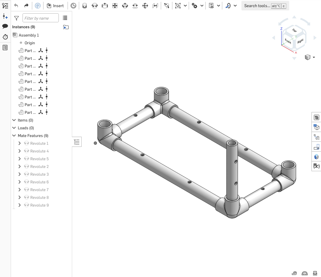
Part 3: Creating a PVC Practice Structure
You will now practice these OnShape skills by creating something using the PVC parts that are in the ROV parts library. You will be the “driver” and “navigator”, and each student should work independently. Here’s how to get started:
-
Click on the Lab 3 Part 3 - Creating a PVC Practice Structure assignment and then click Start Assignment. You will be taken to a new, blank document in Onshape.
-
Click on the Assembly 1 tab.
-
You can now insert parts from the ROV parts library just like in Part 2 of this lab!
This part is intended for you to do on your own after lab ends. But if you get done early, go ahead and get started on this part!
You can design anything you want for this part of the lab. This is just to give you more practice with inserting things from the parts library, and especially with using mates to attach PVC parts together. Here are some ideas about what you could make in OnShape:
- bike holder
- file holder
- plant stand
- set of hooks to hang things
- coat stand
- rack to hang off a bed in a dorm room
- dish drying rack
- anything else you can think of!
Your PVC structure has the following design constraints:
- Minimum of 2 three-way fittings
- Minimum of 2 elbows
- Minimum of 3 tees
- All fitting joints must have a pipe inserted (i.e. you can’t have a tee fitting that only connects two pieces of pipe)
- Minimum dimension in any direction of 4 inches (overall length, width, height)
- Maximum width and length of 11 inches
- Maximum height of 16 inches
- Minimum of 16 straight pieces of pipe
- Maximum of 10 total feet of straight pipe
Make your design in OnShape using the ROV parts library and the skills you gained in this lab. Export images of your model (just like you did with the ROV you made in lab) and create a parts list that includes the types and number of joints and the number and lengths of pipes. Also note the overall dimensions of your PVC structure (length, width, height). You will submit all this in a homework assignment.
This concludes Part 3 of this lab. You DO NOT need to “submit” the assignment on Onshape, but nothing bad will happen if you do. Make sure you complete the Homework questions on PrairieLearn, though!
Version Tracking with OnShape
OnShape has quite robust revision tracking. Every time you finish changes to a document, you can create an official new version of that document with the version tracking button ![]() .
.
If a document contains a part with a newer version, it will ask you if you’d like to update that part to the latest version.
Lab 4: 3D Printing and Operating Agreement
Checklist
| Before Lab | |
| During Lab | |
| After Lab |
Overview
This lab consists of a tour of the various ways to make cool stuff at the Duderstadt Center, including their 3D printing facilities. After the Duderstadt Center tour, your team will create an Operating Agreement. There should be time at the end of lab for your team to do a check-in on how your PDR slides are coming.
Meet at the Information Desk on the first floor of the Duderstadt Center (DC floor map) at the start of lab.
Tour of Duderstadt Center Facilities (50 min)
The Duderstadt Center has a variety of places that you can use to design and build things. There are also places where you can record high quality video and audio to help you communicate to people about your cool thing. You will go on a tour of the various areas and services in the Duderstadt Center and learn how to get access to the facilities they have. Of particular interest will be Fabrication Underground where you can 3D print things – such as a custom part for your ROV!
You are NOT required to 3D print something for your ROV!
Part of designing your ROV is coming up with something new and interesting to test out. That “interesting thing” could be a new way of attaching thrusters, a novel frame design, custom code, a custom part made from materials in the lab, or a 3D printed part (or anything else that you can think of). This overview of 3D printing is meant to teach you some basics about 3D printing so that everyone has the option to 3D print something if they want to.
Creating Your Team’s Operating Agreement (30 min)
An Operating Agreement is a living document that companies use to document the consensus they come to on how to handle a variety of common challenges that arrive when you work with other people. The point of the Operating Agreement is that you come to a consensus on the “ground rules” for handling challenging situations when you are all calm and in a reasonable frame of mind. Then, if one of the challenging situations does arise, you refer back to the Operating Agreement to see what steps should be taken by the team. This process takes the emotional response out of the decision making and keeps the focus on productive solutions.
Tandem includes a scaffolded Operating Agreement for you to complete. Go to Tandem and select “Meet Your Team” (the lesson). Your group should work together on this assignment to make plans for operating procedures that will optimize your team experience.
You all will need to enter text individually, but your team should work together to complete it. You might choose to make a shared Google Document on which you type (and then you can cut and paste your text into Tandem).
Planning Your First Team Meeting Outside of Class (20 min)
Your team’s Preliminary Design Review (PDR) is next week! We’ll be going over the ROV design reviews in our next lecture, but you can read through the PDR presentation requirements listed in the Deliverables document.
Your team will need to meet at least once between our next lecture and your next discussion/lab period to create your PDR slides. Before you leave lab, make sure you and your team have completed these steps to prepare for this team meeting:
- Determined a time to meet (ideally, at least one hour)
- Here are some tools that may be helpful in finding a time to meet:
- Comparing calendars (if everyone has their calendar up to date)
- If everyone on your team is using their U-M Google Calendar as their main personal calendar, you can actually use Google Calendar to overlay everyone’s availability and see what is open
- Our favorite quick-and-dirty, bare-bones website to find times to meet is whenisgood
- Another simple website to find times to meet is when2meet
- Other sites/apps include Doodle and Calendly
- Comparing calendars (if everyone has their calendar up to date)
- Here are some tools that may be helpful in finding a time to meet:
- Choose a location to meet
- We strongly recommend you meet in person!
- The Duderstadt Center, including Mujo Cafe, has lots of group stations for you to use
- You can also find locations throughout campus
- If you are planning to meet sometime on a Saturday, Sunday, Monday, or Tuesday, it’s likely that the ENGR 101 Pierpont labs will available, and those labs have nice group stations with a CAEN computer and monitor to make it easier to do group work.
- Ask your IA where are their favorite places to meet with groups!
- Everyone enter the meeting time and location on your personal calendars
- We strongly recommend having one person create the calendar event and then inviting everyone else. This way, you know everyone has the correct time and location
- Decide what platform you want to use for shared team documents
- We recommend Google Drive for this since that is U-M’s official partner. You might also use Microsoft’s online platform or Dropbox. It doesn’t really matter as long as everyone has access using their U-M account.
- In that platform, have someone create a folder for this ROV team and share it with everyone
- In that folder, have someone else create an agenda document for your meeting; add a link to this document to the calendar invitation
- In the document, have a third person create a preliminary “list of stuff to do” at the meeting.
- A good place to look for “things to do” is what needs to be in the PDR presentation!
Lab 5: Preliminary Design Review & Construction Techniques
Checklist
| Before Lab |
|
| During Lab | |
| After Lab |
Overview
In this lab, you will learn how to work with the basic construction materials for your ROV project. These materials are Commercial Off-the-Shelf (COTS) equipment. There are pros and cons to working with COTS equipment: they are readily available and relatively inexpensive, however you are limited by what shapes, colors, and materials you can buy. So, when you find yourself frustrated because you can’t build what you want to with the provided equipment, think about what kind of piece you need and how you might be able to produce that through 3D printing, laser cutting, CNC-machining, etc.
This is a 3 hour lab.
We’re putting the lab and dicussion time together today so that we have enough time to get through all the teams for their Preliminary Design Review.
Power Tool Training (20 min)
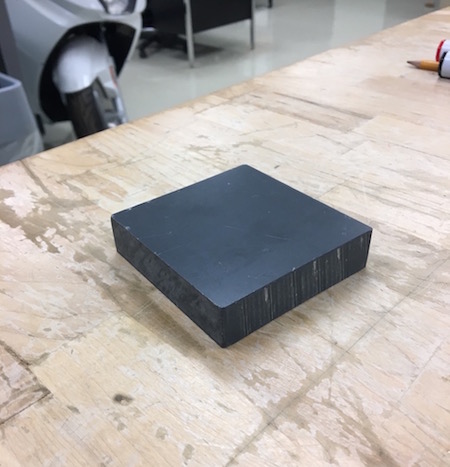
At some point during the lab, Justin will bring your team over to the power tools to train each of you on the different machines that we have. Everyone will use the drill press to drill a hole in a piece of PVC pipe and cut piece of wood on the band saw. This way, everyone can get a feel for how our particular power tools work.
Preliminary Design Review (30 min)
At some point during lab, your team will be pulled out for your Preliminary Design Review.
Constructing a PVC Structure (110 min)
In order to get practice building with PVC pipe before you commit to your actual ROV, your team will build a practice structure/shape today. To make things interesting, you will have some constraints and if you meet them, your team’s shape could win a little competition. Please read this whole section before you start so you know all the considerations and rules involved.
Have fun with this exercise! This is a competition, but your grade does not depend on getting this project perfect. Be excellent to each other; you and your teammates have a lot of work left to do together after today!
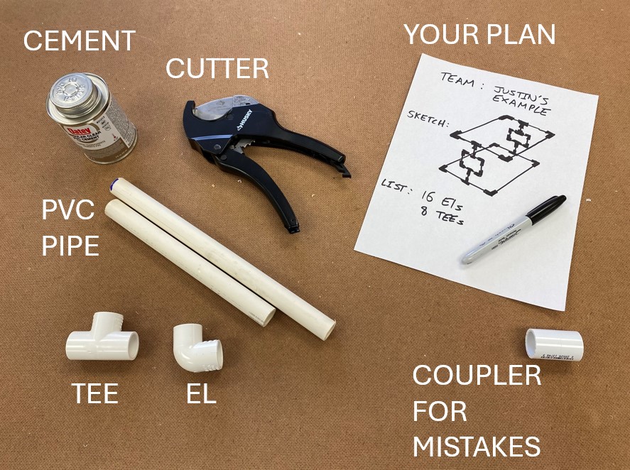
Phase 1: Design and Shopping
In this first step, your team must sketch out a picture of the shape you are going to build. You will also list how many of each part you need to build this shape.
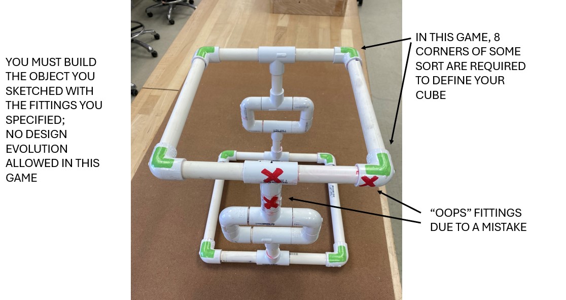
Here are the rules for the shape you are designing:
- Your shape must define a cube that is 12 inches x 12 inches x 12 inches.
- Your shape must have 8 corners that define the limits of that cube.
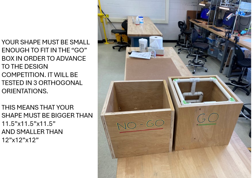
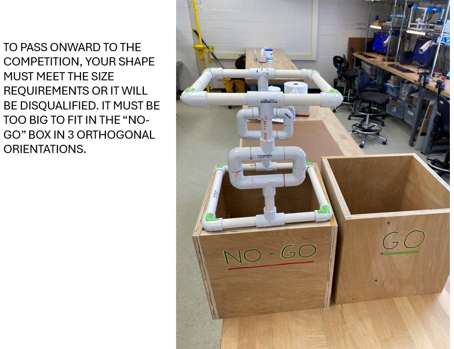
- Your shape must fit inside a 12 inch x 12 inch x 12 inch box (the “GO” box).
- Your shape must be too big to fit inside an 11.5 inch x 11.5 inch x 11.5 inch box (the “NO-GO” box).
- You must build the shape that your team sketches. Your sketch will be initialed by your IA before you begin construction so that you are committed to your design.
- Your IA will control the supply of fittings, and you are limited to the number of fittings required to complete your sketched design. You must have a “shopping list” of fittings required and it must match what is required by the sketch and not be padded with extra fittings.
- You are only allowed to use Elbow and Tee fittings for this challenge.
- You may use as many Elbows, Tees, and pipes as you wish.
- You must cement all the joints before submitting your shape for measurement.
Fig shows your equipment for this PVC challenge. You can also see an example of a design sketch and “shopping list” of how many of each type of fitting you need.
Phase 2: Construction
In this second step, you must now carefully build the structure that you designed in step one. You will have PVC cutters and PVC cement at your station. Measure carefully, as you are very limited with respect to parts.
Here are the rules for constructing your shape:
- You will be allowed 6 mistake fittings in the event that you measure wrong and need to redo something.
- You will be allowed to use couplers as mistake fittings if you wish. They will count toward your 6 extra fittings.
- You must get the “oops” fittings from your IA and it must be noted on your sketch sheet by your IA.
- You may get up to 4 practice fittings from your IA to try cutting and gluing before you work on your actual shape. These may not be saved for your structure. If you get practice fittings, you must use them for practice.
- Aside from altering the shape using the “oops” fittings, once it is built, you may not alter it to fit in the GO and NO-GO boxes. That means no sanding it down, or shaving it with tools, or building it up with tape or other things. If we see evidence that the shape has been cut or shaved down, it will be disqualified.
- You are limited to working on this construction during lab today. In order to keep it consistent, you may not keep working on this during office hours.
Fig shows an example of a constructed PVC shape with “oops” fittings marked. Remember, you must build the shape you designed.
Phase 3: Verification
In order to make it to the design competition, your design must be verified by your IA.
Here are the rules for the verification of your constructed shape:
- Before going into the gage boxes, you must bring your shape and your plan to your IA to verify that what you built matches what you designed.
- Your shape will then be tested in the “GO” and “NO-GO” boxes in different orientations to check whether it meets the challenge criteria (Fig and Fig). If your box fails in one orientation, it’s okay! Don’t be too heartbroken because it was good practice for making your real ROV.
Phase 4: People’s Choice Design Competition
Shapes/structures that meet all the requirements above may participate in the design competition the following week once all the structures are done. Your sketch and your shape will be laid out for all the sections to see, and each person will get a vote. Since all these shapes have met the basic requirements, each person may vote however they please.
You are welcome to write about the virtues of your design on your sketch sheet to try to sell it to the voters. Again, voters may vote on a whim, but here are some considerations to get you thinking:
- Are you going for efficiency or for style?
- Are you going to impress with complexity and tight tolerances?
- Is the shape cool or is it boring?
- Is it tidy or is it a sloppy mess?
- Did you make any mistakes? Are any unions in evidence? Or was it a perfect execution?
- Did your design interpret the rules creatively and push the boundaries of what could be designed?
If you win, glory, fame and riches will be yours. You will be paraded around the Big House in a chariot and showered in rose petals. Not really, alas. But, you will get bragging rights and some candy. Good luck!
Explore ROV Building Materials
At some point during lab, your team should go over to where Justin has samples of the different types of building materials that we have for your team to use to build your ROV. Consider what you have available and use these examples to help you come to a consensus on your ROV design.
POST-LAB
Reflect on these questions and be ready to answer them on the next homework assignment:
- What was the most problematic aspect of the PVC structure, in terms of building it?
- How would you revise this design, now that you have information on how it can be built?
- What aspects of this PVC structure might you incorporate into your team’s ROV design?
- As you designed and built your PVC structure, you may have been unable to construct your ideal design due to limitations of the provided parts. You will have the same challenge with your ROV. Look at your preliminary ROV designs. What are some potential challenges that you will have in constructing this ROV? Where does an innovative, custom part make sense?
Lab 6: ROV Plan & Prep
Checklist
| Before Lab | |
| During Lab | |
| After Lab |
Overview
Now that we have started the ROV project, there are no formal lab instructions for the rest of the semester. Instead, we’ll list some guidelines for each of the ROV labs so that you can compare your team’s progress with where you generally should be each week.
These are guidelines, not rules. If your team is running a little bit ahead or behind these checkpoints/suggested actions, that is totally fine. However, if you find that you’re consistently behind or behind by more than a week, get to Open Lab and get caught up!
- Major goals
- Get your Operating Agreement approved by your IA
- Get your ROV Plan approved by the end of lab
- What to do
- Review your Operating Agreement with your IA, get feedback, make revisions if necessary
- Go through your ROV Plan Checklist (below) with Justin and your IA
- Answer questions
- Make plan revisions based on feedback from Justin/IA
- Repeat until plan is approved
- Reach goals (if you get done early)
- Start listing tasks, deadlines, and task leads (who is responsible for making sure that task is complete); we’ll be doing project planning during the next lecture meeting time
- IF you get approval, you may start building your ROV, but we do not really intend for anyone to begin building this week.
ROV Plan Checklist
To get approval to build your ROV, your team needs to pass this checklist and get approval from Justin and your IA.
- Vehicle design
- Start by just highlighting the overall design: What are three adjectives that describe your vision?
- Frame
- Dimensions: ROV will fit in bin
- Lengths of all PVC pieces specified
- Total length of 1/2” PVC is less than 15 feet
- Number of fittings and of what types
- Number of fasteners and of types (zip-ties, bolts, etc.)
- Are your holes drilled such that the ROV can vent its air at the highest point?
- How are the payload canisters mounted/supported? Is there room for the wires to be fixed back without being pulled tight?
- Thrusters
- placement specified (and enough flow around them)
- Protection
- Mounting is sufficient:
- Can you attach the thruster the way your model says?
- If so, will the attachment be of sufficient strength?
- Can you get the thruster back off at the end of the project?
- Cable management
- Wires have slack/are not pulled tight
- Camera
- How is the camera protected?
- Can you get the camera back off at the end of the project?
- How does your camera placement support how you are going to drive your ROV?
- Buoyancy
- What material(s) are you using?
- How are you attaching it?
- Where is your buoyancy flexibility/adjustment? (placement and amount)
- Controller design
- Start by just highlighing the overall design: What are three adjectives that describe your vision?
- Hardware
- Number of buttons/switches
- Buttons/switches will fit where they are intended to go
- Are you using something other than buttons/switches? If so,
- What are you using?
- Do you understand the interface? (this is your job!)
- Software
- Are you using stock code or custom?
- For custom code
- What are your algorithms?
- How will you implement and test this code?
- What happens if you can’t get your code to work? What are your backup plans?
- Order of assembly
- What is the largest # of joints you’ll have to make simultaneously to put this together?
- Custom part(s)
- Do you need to create any custom parts?
- If so, what are the strength requirements? (Does it carry a load? If so, how will you test it?)
- Deployment
- Can you get in and out of the water in less than 5 minutes?
- What’s pre-assembled in the box, and what do you have to do for deployment? (is there a specific order those things have to be done in?)
- How many fasteners/what type will be added in those 5 min?
- Servos (if using)
- All thrust/structural loads must be supported by ROV chassis, not the servo. (Are yours?)
- How are you going to isolate these loads?
- What’s your plan if the servo fails?
Prepare for DDR Presentation
This means that you have to have a final team design for your ROV system (vehicle and controller) that your team has come to a consensus on. If your team hasn’t already figured out the design you’re going to build, now is a great time to keep talking that through and hopefully get everything finalized.
If your team has come to a consensus on the design for your ROV system, then you should take a look at where you stand with the slides for your DDR presentation. If you haven’t started these slides, then start a file for them now and share it with everyone on your team. You might also share it with your IA and your peer mentor so you can ask them for their feedback later on.
Review the DDR presentation requirements listed in the Deliverables document. Make sure you have all the requirements! If you’re missing anything, make a slide for the missing item as a placeholder, and leave a comment to yourselves so you remember to finish the slide.
Lab 7: Detailed Design Review
Checklist
| Before Lab | |
| During Lab | |
| After Lab |
Overview
- Major goals
- Conduct Detailed Design Review
- Finalize Task List and Build Plan for your ROV
- Start on frame
- Start on controller
- Start on controller code
- Develop back up plans for if any of your subsystems don’t work at the showcase (custom thruster protection fails, etc.)
- Develop back up plans for if any of your subsystems don’t work at the showcase (servo fails, custom thruster protection fails, etc.)
- What to do
- If your ROV plan wasn’t already approved, complete this task first
- Start executing your ROV plan!
- Things to remember
- It is a lot easier to document your ROV as you go along. Make sure you are taking pictures and video every time you meet to work on the ROV!
- Rotate people through both the actual build roles and the documentation/verification roles.
- Update your CAD model as you go along so that the final CAD model matches what you actually built.
- With 15 minutes left in lab
- Put away all tools and material
- Reconvene team
- Make sure each person knows when the team is meeting next and what action items they need to have done by then
This is a 3 hour lab.
We’re putting the lab and dicussion time together today so that we have enough time to get through all the teams.
Detailed Design Review
At some point during lab, your team will be pulled out for your Detailed Design Review.
Lab 8: ROV Build & Thruster Testing
Checklist
| Before Lab | |
| During Lab | |
| After Lab |
Overview
- Major goals
- Complete thruster testing
- Make significant progress on your ROV, including frame, controller, and code
- Update Critical Design Review Slides with pictures of ROV frame and controller and updated ROV calculations
- What to do
- Continue executing your ROV plan!
- Follow the instructions below to measure the thrust produced by each of your thrusters. You need this data for your CDR presentation next week!
- Things to remember
- Continue to document your ROV and update your CAD model, if necessary
- If you have downtime, like while you are waiting for PVC cement to fully harden, work on your ROV calculations.
- With 15 minutes left in lab
- Put away all tools and material
- Reconvene team
- Make sure each person knows when the team is meeting next and what action items they need to have done by then
Measuring the Thrust Provided By Your Thrusters
A thrust stand is set up at the testing tank in lab. This stand will allow you to test each of your ROV thrusters in both the forward and backward direction to get their actual measured thrust. You can then use these measurements to help you decide where to place your thrusters on your ROV.
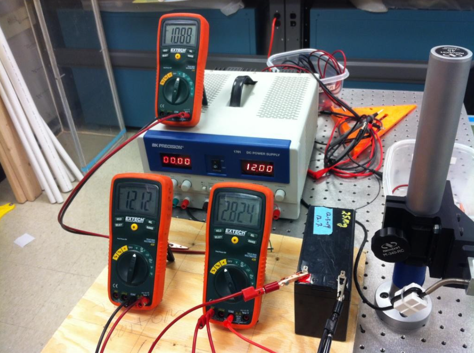
Equipment:
- Power supply set to exactly 12.00V to power load cell
- Load cell
- 12V SLA battery
- 3 DVMs, one for battery voltage, one for batter current, one to read load cell.
- Lever arm with bearing
- Optical table and hardware to mount load cell
- Wire for tension hookup
- Clamp for thrust arm bearing.
Fig and Fig show what the thrust stand looks like.
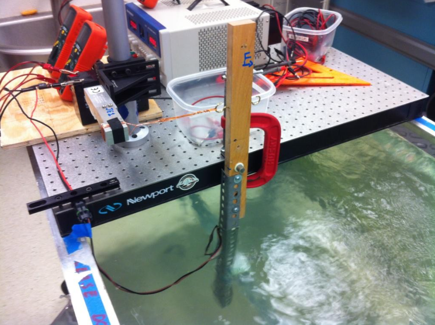
Follow these directions to measure the thrust of one of your thrusters:
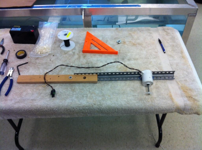
- Attach a thruster to the metal end of the arm with a cable tie through the marked holes.
Thruster attachment - Install the thrust arm on the bearing. Make sure bearing is lubricated.
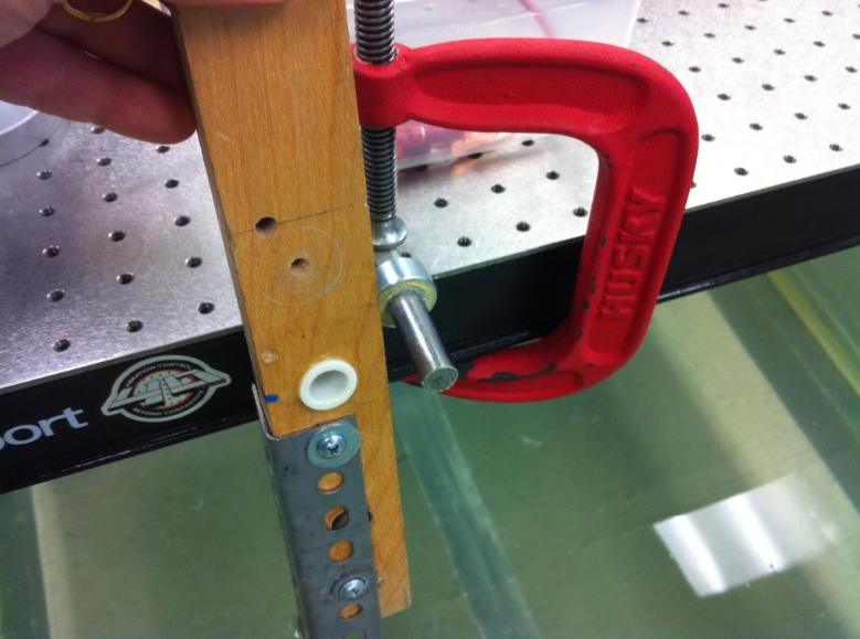
Sleeve and bearing shaft 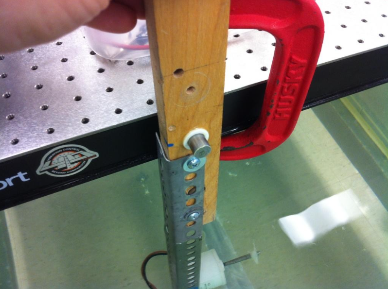
Slide arm onto bearing 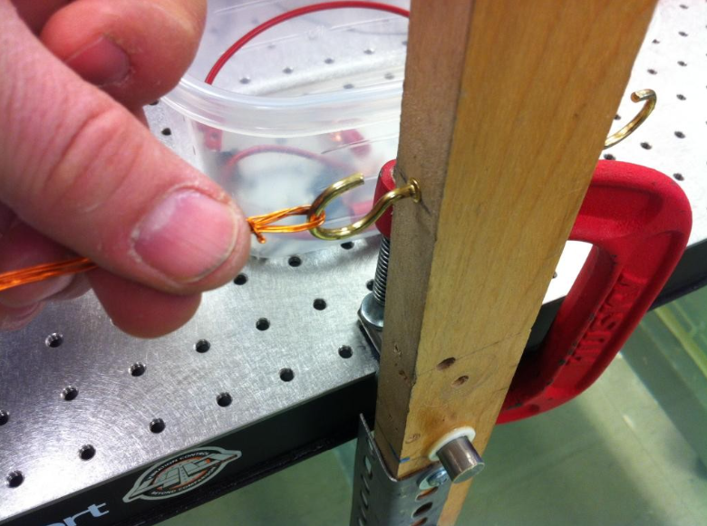
Connect wire harness from load cell to hook - Plug the thruster in and connect the battery to power the thruster, read load cell voltage, battery voltage and battery current.
- To read reverse thrust, remove and reverse thrust arm, connect battery with leads reversed to reverse direction of motor rotation and read voltages and current.
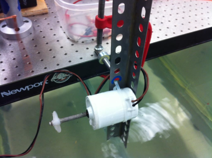
Thruster arm reverse direction 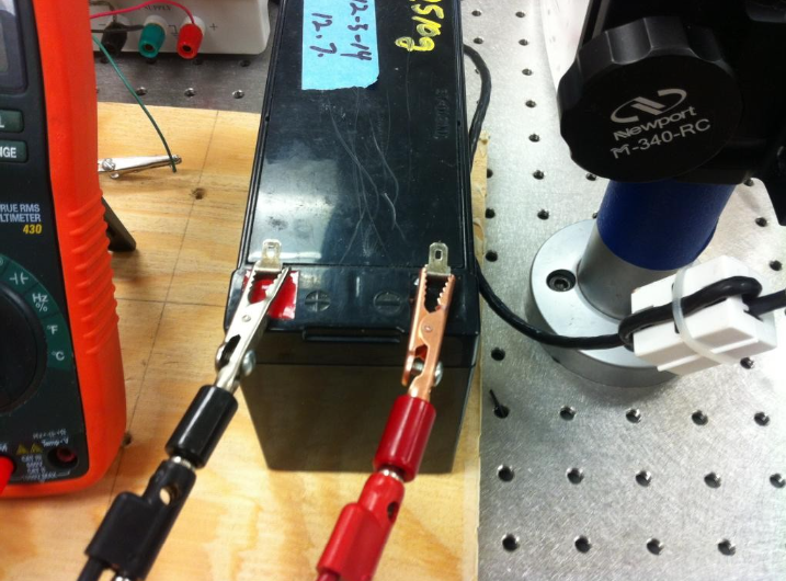
Reverse battery leads for reverse test
For Fall 2019, load cell calibration equation is:
$N$ = -57.1354 + 52.84 $V$
where $N$ = newtons and V = volts (not millivolts!)
Lever arm length pivot to thruster = 37.8 cm
Lever arm length pivot to load cell = 12.7 cm
Note that the thruster is producing a thrust which is the load cell force times the ratio of upper lever arm to the lower level arm.
Lab 9: ROV Build
Checklist
| Before Lab | |
| During Lab | |
| After Lab |
Overview
- Major goals
- Make significant progress on your ROV, including frame, controller, and code
- What to do
- Continue executing your ROV plan!
- Try to get as much done on your controller this week as possible. You want plenty of time to make adjustments and practice driving around your ROV!
- Things to remember
- Continue to document your ROV and update your CAD model, if necessary
- If you have downtime, like while you are waiting for PVC cement to fully harden, work on your ROV calculations.
- With 15 minutes left in lab
- Put away all tools and material
- Reconvene team
- Make sure each person knows when the team is meeting next and what action items they need to have done by then
Lab 10: ROV Build
Checklist
| Before Lab | |
| During Lab | |
| After Lab |
Overview
- Major goals
- Complete ROV including frame, controller, and any custom code
- What to do
- Continue executing your ROV plan!
- You are trying to get your ROV “finished” this week so that you can test the completed system next week. You want plenty of time to make adjustments and practice driving around your ROV!
- Things to remember
- Continue to document your ROV and update your CAD model, if necessary
- If you have downtime, like while you are waiting for PVC cement to fully harden, work on your ROV calculations.
- With 15 minutes left in lab
- Put away all tools and material
- Reconvene team
- Make sure each person knows when the team is meeting next and what action items they need to have done by then
Lab 11: ROV Testing at GFL
Checklist
| Before Lab | |
| During Lab | |
| After Lab |
Overview
- Major goals
- Test ROV in the water
- Verify that all systems work as intended, including any custom code
- What to do
- Each team will have at least 20 minutes of uninterrupted time in the test tank in 108 GFL to
- Test ROV controls
- Observe ROV’s behavior
- When not testing
- Create a plan for how to efficiently collect data during the showcase
- Finish any ROV subsystems that need completing
- Work on your final presentation, innovation video, and final report
- Complete the pre-MHL cost worksheet and submit to Canvas
- Each team will have at least 20 minutes of uninterrupted time in the test tank in 108 GFL to
- Things to remember
- We will have at least one open lab time after this lab. If your testing didn’t go as well as you had hoped, or if there is additional testing/practice you’d like to do, make sure you sign up for some time during open lab.
- Next week is the showcase! Make sure you take this into account when setting up your next meeting times and in scheduling tasks for the showcase, final presentation, innovation video, and final report!
- With 15 minutes left in lab
- Put away all tools and material
- Reconvene team
- Make sure each person knows when the team is meeting next and what action items they need to have done by then
Project Gate: If you have custom code, it must be verified to work in the 108 GFL lab or you will not be allowed to use that custom code at the MHL.
Lab 12: ROV Testing at MHL
Checklist
| Before Lab | |
| During Lab | |
| After Lab |
Overview
- Major goals
- Test ROV in deep water
- Verify that all systems work as intended
- Practice driving the ROV in deep water
- Measure speed in 2-3 different directions of travel
- Test showcase data collection plan
- Determine roles for the showcase (data-taker, driver, cable management, spotter, video monitor holder, whatever works for your team)
- What to do
- This lab is on Central Campus!
- Follow the ROV Testing at MHL Procedures.
- Things to remember
- The MHL is a working laboratory! Be careful where you step, move slowly, and watch out for each other at all times
- There is absolutely NO jumping around on the carriage or sub-carriage.
- Laura has the right and the responsibility to kick you out of the MHL if you are behaving in an unsafe manner. Please do not make her do this.
- The battery on the ROV will eventually start to drain down. Don’t wait too long to do your speed measurements.
- With 15 minutes left in your lab session
- Take your ROV out of the water
- Remove the payload and camera
- Put your ROV back in its bin but leave the lid off so it can dry out
- Put away all tools and material
- Reconvene team
- Make sure each person knows when the team is meeting next and what action items they need to have done by then
- You can leave when your IA has inspected your station and says you can leave
Lab 13: ROV Tear Down & Finish Documentation
Checklist
| Before Lab | |
| During Lab | |
| After Lab |
Overview
- Major goals
- Swing the ROV to get final CG location
- Get any final pictures or video that you need for your final report and innovation video
- Tear down ROV and return all reusable parts to their proper bin
- Clean out your ROV bin
- Work on ROV final report and innovation video
- What to do
- Follow the instructions below to swing your ROV
- Check your shot list/storyboards/script for your innovation video; identify what shots you still need to get with your ROV
- Take pictures and/or video that you need
- Gently detach all reusable parts of your ROV, including but not limited to: the thrusters, hose clamps, bolts, floats, foam, mesh, etc.
- You can take the PVC frame with you if you want to (otherwise, we will just throw it away)
- Clean out your ROV’s bin, sorting items into reusable, recyclable, and trash
- Spend the rest of the time working on your final report and innovation video
Swinging the ROV to Determine Center of Gravity (CG)
Onshape will calculate an overall Center of Gravity (CG) and Center of Buoyancy (CB) for you using the weighted average method. However, you need to verify these calculations experimentally.
There will be a cord suspended from the ceiling for you to use to swing your ROV and calculate its CG. Make sure your ROV has the payload canisters installed and is “ready to go” so that you can get the most accurate measurement of its CG.
You will need to swing the ROV three times, each time in a different orientation, so that you can measure the LCG, VCG, and TCG.
The equation for converting the period of oscillation to a distance only works for very small angles. So, just pull the ROV a little bit to the side and then release it to swing.