ENGR 100-600 | University of Michigan
ROV Project Background
This document provides background information on your ROV project. Refer back to this document often as you go through the ROV project.
Remotely Operated Vehicles (ROVs)
Our design-build-test-communicate project in this class involves the building of a remotely operated vehicle (ROV). ROVs are unmanned, powered vehicles controlled by a person (or team of people) on ship or shore. Because ROVs are unmanned, they can be designed to withstand higher pressures than a human, and thus have the capability of descending much deeper than human divers. Because ROVs are powered, they can be used for detailed exploration of the ocean, including taking pictures, recording video, and bringing back samples of ocean water or sediment cores. An example of an ROV is shown in Fig.
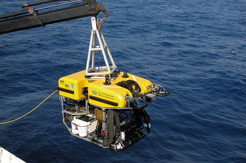
Generally, ROVs are tethered to a ship. The tether provides both power and control to the ROV from the ship and also allows for data transfer from the instruments on the ROV to computers on board the ship. ROVs are driven by a human who is located on board a ship. The human “drives” the ROV by watching what they see from the video cameras located on the ROV. At a minimum, the human operator can control forward and backward movement, up and down movement, and turning.
ROVs can look very different depending on what purpose they have been designed for. If the ROV needs to be maneuverable and fit in tight spaces, it will be smaller and more compact. If the ROV needs to carry a lot of equipment, the ROV may look more like a big cage, so there are lots of attachments points for cameras, lights, sensors, robotic arms, etc.
The first ROVs were developed primarily for military use, such as retrieving practice torpedoes and investigating mines. Other ROVs were developed by industry to aid in things like offshore oil exploration, and by science to aid in research. A famous ROV, Argo, was used to discover the shipwrecks of the RMS Titanic and the German battleship Bismarck.
Component Systems
Any vessel is made up of smaller, less complex component systems. In a car, these component systems can include: the drive train, safety response, fuel delivery, steel structure, anti-lock brake system, etc. In a ship, they can include, the structure of the ship, cargo loading, dynamic seakeeping response, powering, mooring, etc.
Your ROV can also be broken down into component systems such as:
- controller
- frame
- camera mount
- thruster placement
- etc.
Breaking a system down into component systems allows a manager to assign more appropriate tasks to the members of their team according to the abilities of the different people involved in the project. The manager, or project leader, must keep in mind that these component systems will have to work together in harmony to create a successful end deliverable.
Bill of Materials
A bill of materials (BOM) is a list of everything the ROV is made of and carries. For this class, we will use the Bill of Materials to document everything about the ROV, including the type of item, the individual cost per item, how many of each item are used, and the total cost per item type. The full bill of materials can be quite complex, so let’s look at when it is appropriate to use a detailed bill of materials and a simplified bill of materials.
Detailed Bill of Materials
A detailed bill of materials lists the number and cost of every individual part that goes into building the vessel along with a breakdown of its cargo. A detailed bill of materials is appropriate within engineering departments and for written reports. Part of an ROV’s detailed bill of materials might look like Table.
| Item | Cost | Unit | Quantity | Cost |
| Thrusters | $40.00 | ea | 4 | $160.00 |
| Hose Clamp | $3.79 | ea | 4 | $15.16 |
| 3 Way Corner | $1.85 | ea | 8 | $14.80 |
| Plastic Box | $14.49 | ea | 1 | $14.49 |
| 1/2" Pipe | $1.02 | per foot | 11.25 | $11.48 |
| Toggle Switch | $2.25 | ea | 4 | $9.00 |
| Nylon Bolt | $1.59 | ea | 4 | $6.36 |
| Cross | $1.32 | ea | 4 | $5.28 |
| M-library bottle | $4.99 | per bottle | 1 | $4.99 |
| Small Hose Clamp | $2.04 | ea | 2 | $4.08 |
| Zip Tie | $0.08 | ea | 42 | $3.36 |
| Tee | $0.44 | ea | 7 | $3.08 |
| Push Button | $1.39 | ea | 2 | $2.78 |
| PVC Cement | $0.05 | per joint | 46 | $2.30 |
| Wire | $0.10 | per foot | 23 | $2.30 |
| Steel Cylinder Ballast Weight | $1.00 | ea | 1 | $1.00 |
| Elbow | $0.38 | ea | 2 | $0.76 |
| Pink Foam Board | $0.06 | per sq. in. | 10.5 | $0.63 |
| Total | $261.85 |
Simplified Bill of Materials
A simplified bill of materials lumps together the individual parts and cargo into broad categories and provides a total cost per category. A simplified bill of materials is appropriate for presentations and memos to executives. A simplified bill of materials for an ROV might look like Table.
| Category | Cost |
| Power & Thrust | $225.00 |
| Frame | $42.15 |
| Control | $32.86 |
| Ballast | $5.22 |
| Miscellaneous | $2.90 |
| Total Cost | $308.13 |
A Note on Including Mass (or Weight) in a Bill of Materials
When you design something a lot bigger than our ROVs, such as a car or plane or ship, you will also need to keep track of the mass (or weight) of each part of your design. This is especially important for something like a ship where you will need to make sure the ship’s weight isn’t greater than its buoyancy, and you can’t put a giant ship on a scale to see how much it weighs! However, our ROVs are so small that we will be able to weigh the entire vehicle using a scale. And you will be able to check for neutral buoyancy just by putting the ROV in the water and seeing if it floats or sinks. So, we will only include the cost breakdown in the bill of materials for this ROV project.
ROV Design Considerations
The main components of an ROV are:
- a controller for driving the ROV
- a tether that connects the controller (on land) with the ROV (in the water)
- a structural frame
- thrusters that move the ROV
- anchor points and space for instruments/cargo
Some things to keep in mind when designing your ROV are:
- is speed more important? or maneuverability?
- should the ROV be neutrally buoyant? (i.e. the net buoyancy is zero)
- weight limits
- power limits
- placement of the thrusters
Note that we have an advanced ROV tether system in this class. A lightweight tether connects the ROV to a float on the surface of the water. This float has antennae that receive wireless signals from your controller and that transmit video back to your controller. This semi-tetherless approach allows our ROVs greater maneuverability and flexibility in their missions.
Servos
We have waterproof servos for you to use on your ROVs if you want to. The servo (short for servomotor) is a motor that rotates a short plastic arm back and forth. You control the rotation using a potentiometer – a knob that you turn back and forth. If you choose to use a servo, know that the servo must operate via cable or wire linkage. Meaning, you have to connect a wire from the servo’s arm to whatever part of your ROV that you want to move. You can’t mount anything directly to the servo’s arm. Also, when the servo is turned off, whatever ROV part the servo controls should be balanced and supported at rest. If you are interested in learning more about servos, ask your IA at the beginning of the ROV project to show you a servo and explain how to use one. Then, you and your team can decide if you want to incorporate a servo into your design.
Provided Material for Building Your ROV
We will provide a variety of material for you to use in building your ROV. The payload and camera are provided as stand-alone equipment; all you need to do is connect the thrusters to the payloads thruster cables and it is ready to power your ROV. The following sections give a little bit more detail about the material you have to use to construct the rest of the ROV system.
The Frame
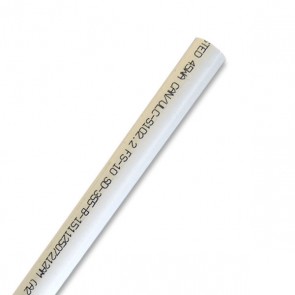
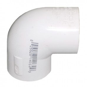
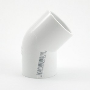
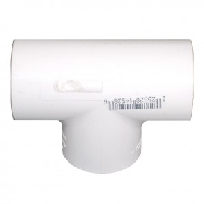
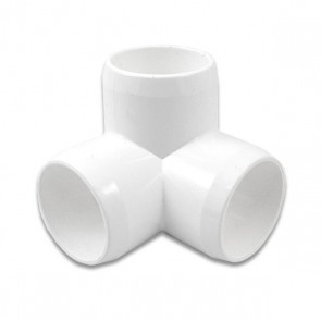
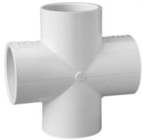
We provide your team with 1-inch diameter schedule 40 PVC pipe and fittings with which to build your frame. Schedule 40 PVC is a commonly sourced material that is relatively straightforward to work with to build basic shapes. The pipe and fittings are cemented together using PVC cement; this forms a very strong bond. Fig shows a diagram of how the pipe fits into the fittings. There is an overlap that you need to be aware of when constructing your ROV frame. Examples of the straight pipe and some common fittings are shown in Fig - Fig.
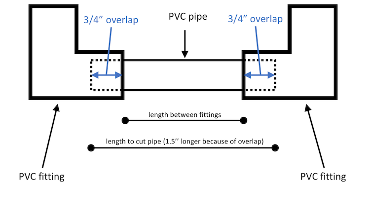
PVC Pipe and Fittings
Thruster Shrouds
If your thruster will be placed outside of the main frame, then you will need to use a thruster shroud to protect the propeller from accidental damage and to prevent the tether from being tangled in the propeller. We have basic thruster shrouds for you to use. An example of a basic thruster shroud is shown in Fig.
You can easily insert your thruster into one of these shrouds and “lock” it into place using the slot that is drilled out for the wires from the thruster. See Fig for an example of what this looks like.
The Control System
The ROV your team will construct carries four constant speed, reversible thrusters for travel and maneuvering. It can support the operation of two servo controllers for mechanical action. It also carries a 400-line self-illuminating NTSC color video camera as its primary inspection instrument. The motors and servos are controlled by an Arduino microcomputer carried in the ROV payload and controlled via wireless radio link to a shore-side hand-held operator’s console. Since radio waves – especially high frequency radio waves such as in typical radio transmissions – have very little penetrating power through water, your ROV must tow an antenna buoy that carries both the radio control and video broadcast signals to a pair of antennae that remain on the surface while the ROV maneuvers submerged. Though it is connected to the surface via the buoy and its tether, your ROV otherwise operates completely untethered from the shore.
The handheld operator’s console also contains an Arduino which translates the information from the control switches you install on the console into a steam of data sent to the ROV via radio transmission. Your team will construct your own customized handheld controller console to operate your ROV.
Components of the Control System
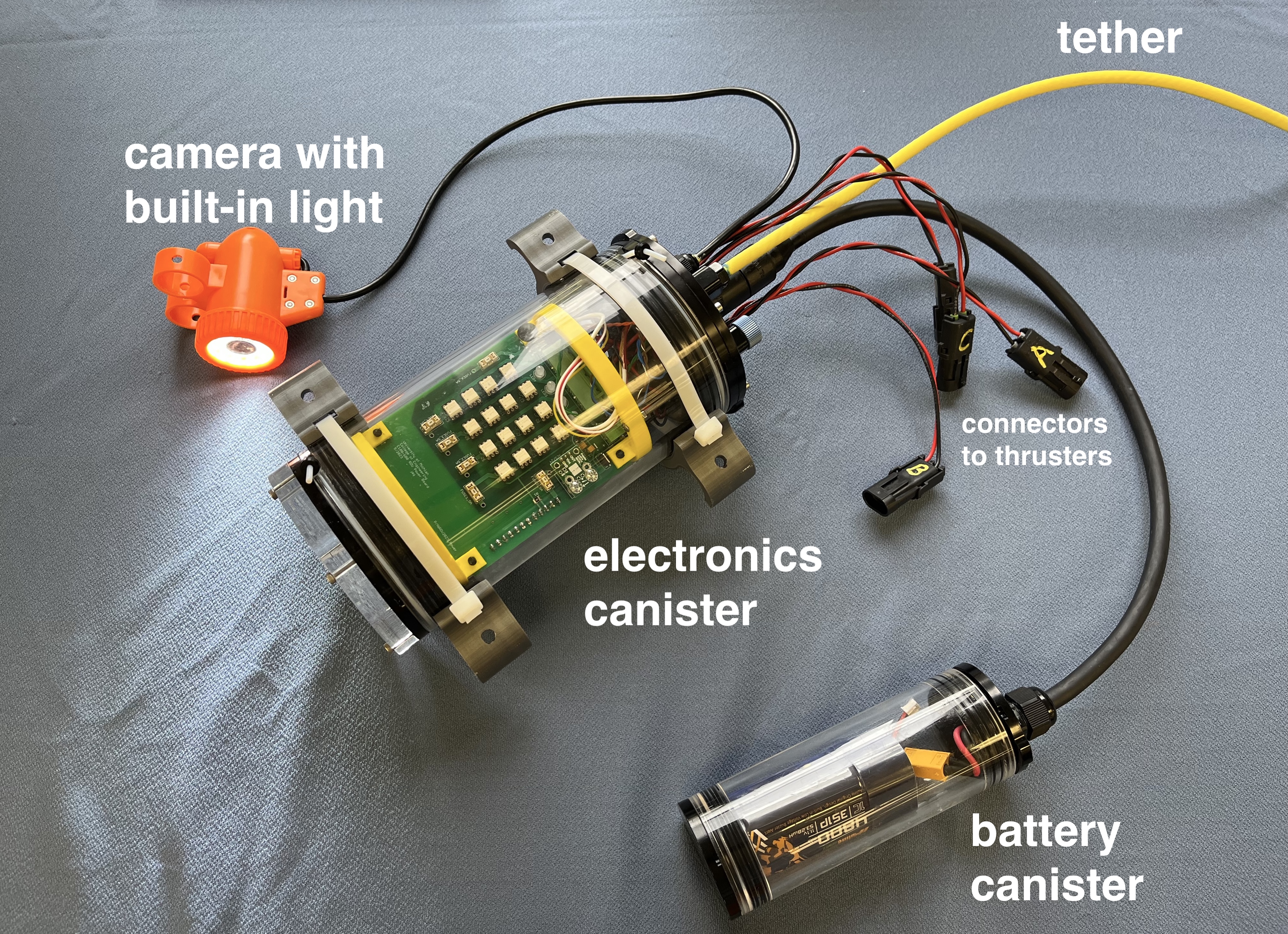
Your ROV will use a custom-designed control system that handles the powering of the thrusters and sending data streams to and from the ROV and the controller that you will build. The entire control system consists of:
- Electronics canister
- Battery canister (connects via short cord to electronics canister)
- Camera with built-in light (connects via short cord to electronics canister)
- Connections to the thrusters (from the electronics canister)
- Tether and float (tether connects to electronics canister)
- Antenna for controller
- Circuitry for controller
The components of the control system are shown in Fig.
An example of a controller that could be built to control the ROV is shown in Fig.
You will learn a lot about this system through experiments in lab and then through trial and error in building your ROV. It’s good to be familiar with all the main components from the start, though!
The ROV Payload
The ROV payload contains a subset of the ROV control system components. Specifically, the ROV payload includes:
- The electronics canister
- The battery canister
- The camera
Fig shows what the payload looks like when it is powered up and ready to be installed on your ROV.
When you are designing your ROV, you will want to keep in mind that you have these three items that must be quickly attached to your ROV frame (electronics canister, battery canister, and camera) and that you will have a short amount of time to do this at the ROV showcase. Think of how you can approach your ROV design with “modularity” in mind!
Hand-held Operator’s Console – aka the Controller
You will design and build a controller for your ROV. This controller communicates wirelessly with an antenna that is mounted on a float attached to the ROV’s tether – thus creating a “semi-tetherless” ROV. The provided equipment for your controller includes is summmarized in Table.
| Item | Example |
| blank controller | 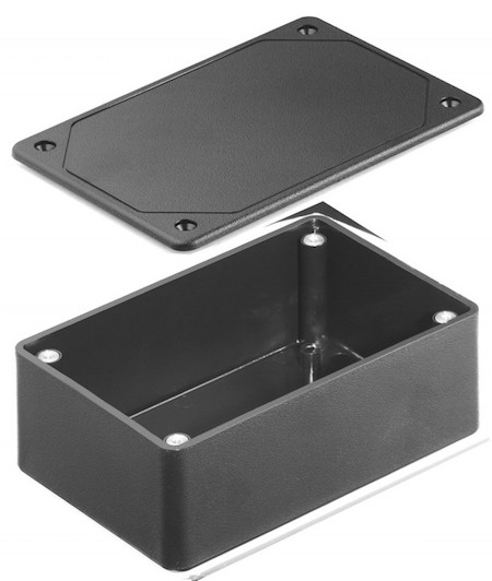
|
| toggle switches | 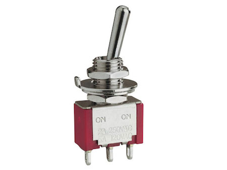 |
| push buttons | 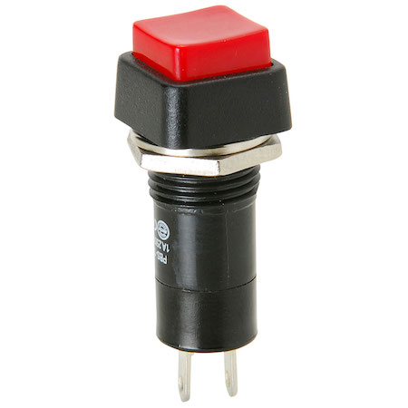 |
| Arduino with breadboard | 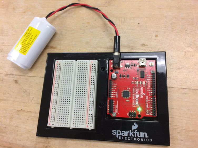 |
Thruster Control
Each thruster can operate in both forward and reverse direction (variable speed operation is NOT available with this hardware system). The Arduino in the payload uses 8 digital outputs to control a solid state relay array that switches battery power to the thrusters. Each digital output turns on one thruster in one of two directions; 4 thrusters $\times$ 2 directions each = 8 control lines. If the forward and reverse signals are both sent to the same thruster simultaneously, it does not turn on at all.
The Arduino in the handheld console (Fig) reads the positions of a set of switches (or other actuators) you install on your console to determine which control signals to tell the Arduino in the payload to turn on. We provide you with an Arduino with a “stock” program based on control using simple push button or toggle switches for each thruster, but you may customize the control logic and switching system if you know how to program an Arduino.
While we encourage teams to be creative in programming their controller, we will not be teaching any programming in this course, so this will be a self-supported endeavor. If things do not work out as expected, you can always fall back to the stock hardware and programming.
Connecting the buttons and toggle switches directly to the Arduino is do-able, but very tricky, and the connections will not be robust (translation: they could break a lot and make everyone very frustrated). Instead, we will use a breadboard (Fig) as an intermediary.
When constructing your controller/operator’s console, you will connect the buttons and switches to the breadboard and then connect the breadboard to the Arduino. We will use a common half-size prototyping board. Here is how it works:
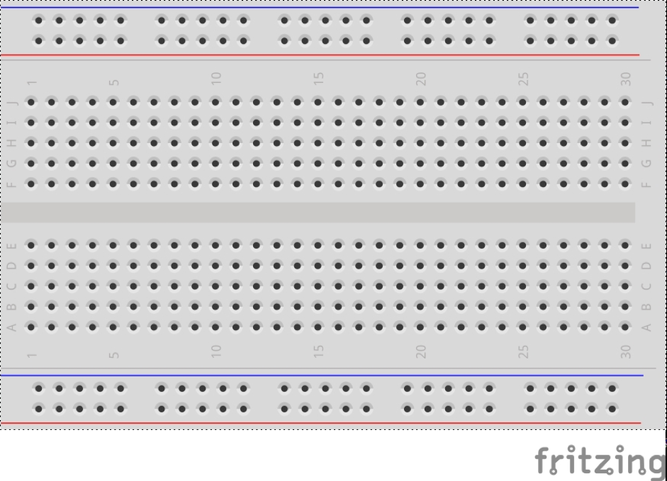
- Each group of 5 holes in a vertical line (as oriented in Fig) are all connected internally to each other. If you plug the end of a wire into hole B5, then a wire pushed into A5, C5, D5, or E5 will be connected to it, and all of them to each other, but no others.
- (A-E)5 do NOT connect with (F-J)5. This is so an integrated circuit can be placed along the “trench” down the middle without shorting the contacts on its opposite side to each other.
- The horizontal rows of holes along the red and blue lines connect internally along the whole width of the board. A wire pushed into any hole along the lower red line will connect to a wire pushed in anywhere else along the lower red line. Same for the blue line. These long lines of connections are intended to be used as power and ground “buses.” When you build circuits, you often need lots of connections to power and to ground.
- The power and ground lines on the bottom DO NOT connect to the power and ground lines on the top. The two sets of long connections are completely independent.
- None of the holes in the (B-J)(1-30) grid connect to the power and ground rows at all.
In lab, you will get practice working with breadboards and Arduinos before you need to build your controller, so you will have a chance to become familiar with how all this works.
The “Standard” System
In the standard control scheme, a single thruster is controlled using either two push buttons (one to go forward, one to go in reverse) or by one toggle switch (flips forward for forward, flips back for reverse, and is off in the center position). A single push button is read by the console Arduino as telling it to have the ROV payload activate one of the eight motor output control lines. In the simplest configuration using a toggle switch, its two positions actuate each of the payload’s two control lines for one motor – forward and reverse.
How an Arduino “Reads” a Switch
In a mirror of the Arduino in the payload, which has 8 motor output lines, the Arduino in the control console has 8 switch input lines:
-
If no voltage is applied to an input line, the Arduino reads that line as “off” and signals to the ROV to turn that output line off.
-
If 5V (5 volts - the Arduino’s internal operating voltage) is applied to the input line, then the Arduino reads that line as “on” and signals the ROV accordingly.
If we take 5V from the Arduino’s voltage supply line and put it to one lead of a push button switch, which is a single-pole-single-throw switch, a switch that simply closes a single connection – connecting its single input to its single output, and wire the other side of the switch to an input pin of the Arduino, then when the button is pushed and the switch closes, 5V will be applied to the pin and the Arduino will read the input line as “on”.
A toggle switch is what is called a single-pole-double-throw switch. Single pole because it operates only on a single circuit path, double throw because it switches the connection of its input line to either of two separate output lines. If the 5V supply is wired to the center pole of the toggle, it can switch the 5V onto either of its two output legs. If those two outputs connect to the Arduino input lines for forward and reverse for one thruster, then the toggle acts to run that thruster forward and reverse when it is toggled back and forth.
Another way to think about “poles” and “throws” is that poles represent multiple switches that operate in parallel on separate circuits in a single housing with a single actuator. Throws represent how many different positions a switch actuator can be placed in, representing different results for what the switch does, for instance a rotary switch on a fan that has multiple positions to select multiple speeds.
“Pulling Down” the Arduino Input Pins
When the switches are not closed in our circuit, nothing at all would be connected to the Arduino input pins. These are sensitive circuits (i.e. high impedance) and stray electric fields in the environment might make them sense enough voltage to think they should be on. To keep the inputs off when we want them off, we connect them to circuit ground through a relatively high value resistor (10,000 $\Omega$). This resistor is large enough that it does not drain off much current when we close the switch, but small enough to keep the input “pulled” down to zero volts (at ground) against ambient noise when our switches are in the open position.
Estimating the Speed of Your ROV
You will need to estimate your ROV’s speed for your progress report. To estimate speed, first calculate the forward thrust provided by your thrusters in the ROV subsystems lab. Next, assume that thrust, $T$, equals drag, $D$:
\begin{equation} T=D \label{eq:ROVdrag1} \end{equation}
Following along with what we know about drag, the drag of your ROV can be estimated using this equation:
\begin{equation} D = C_D \frac{1}{2} \rho A_{ROV} V^2 \label{eq:ROVdrag2} \end{equation}
where $C_D$ is the drag coefficient, $\rho$ is the density of water, $A_{ROV}$ is the maximum cross-sectional area of the ROV, and $V$ is the unknown speed of the ROV.
Substituting Eq. \ref{eq:ROVdrag2} into Eq. \ref{eq:ROVdrag1}, gives this estimate for speed:
\begin{equation} T = D = C_D \frac{1}{2} \rho A_{ROV} V^2 \nonumber \end{equation}
\begin{equation} V = \sqrt{\frac{T}{C_D \frac{1}{2} \rho A_{ROV}}} \label{eq:ROVTopSpeed} \end{equation}
$A_{ROV}$ can be measured from your design. Measure the thrust produced by each of your thrusters in lab using the thrust testing rig. Then calculate $T$ by taking the total thrust produced by your thrusters when traveling in the forward direction (i.e. surge) – 2 thrusters going forward? 3? 4? One that is “on” in the forward direction and one that is “on” in the backward direction? Whatever is correct for your design. $C_D$ should be estimated based on the shape of your ROV. Research different values of $C_D$ for different shapes and choose the one (or combination of $C_D$s) that you feel best describes your ROV. Include your rationale for choosing in the progress report.
Eventually, you will measure the actual speed of your ROV at the Marine Hydrodynamics Laboratory. You will then compare your estimated speed to the measured speed and discuss why they are similar or different. If you have time at the MHL, you should measure the speed of your ROV in different directions (e.g. up, down, forward, backward) and calculate a $C_D$ for each direction of travel.
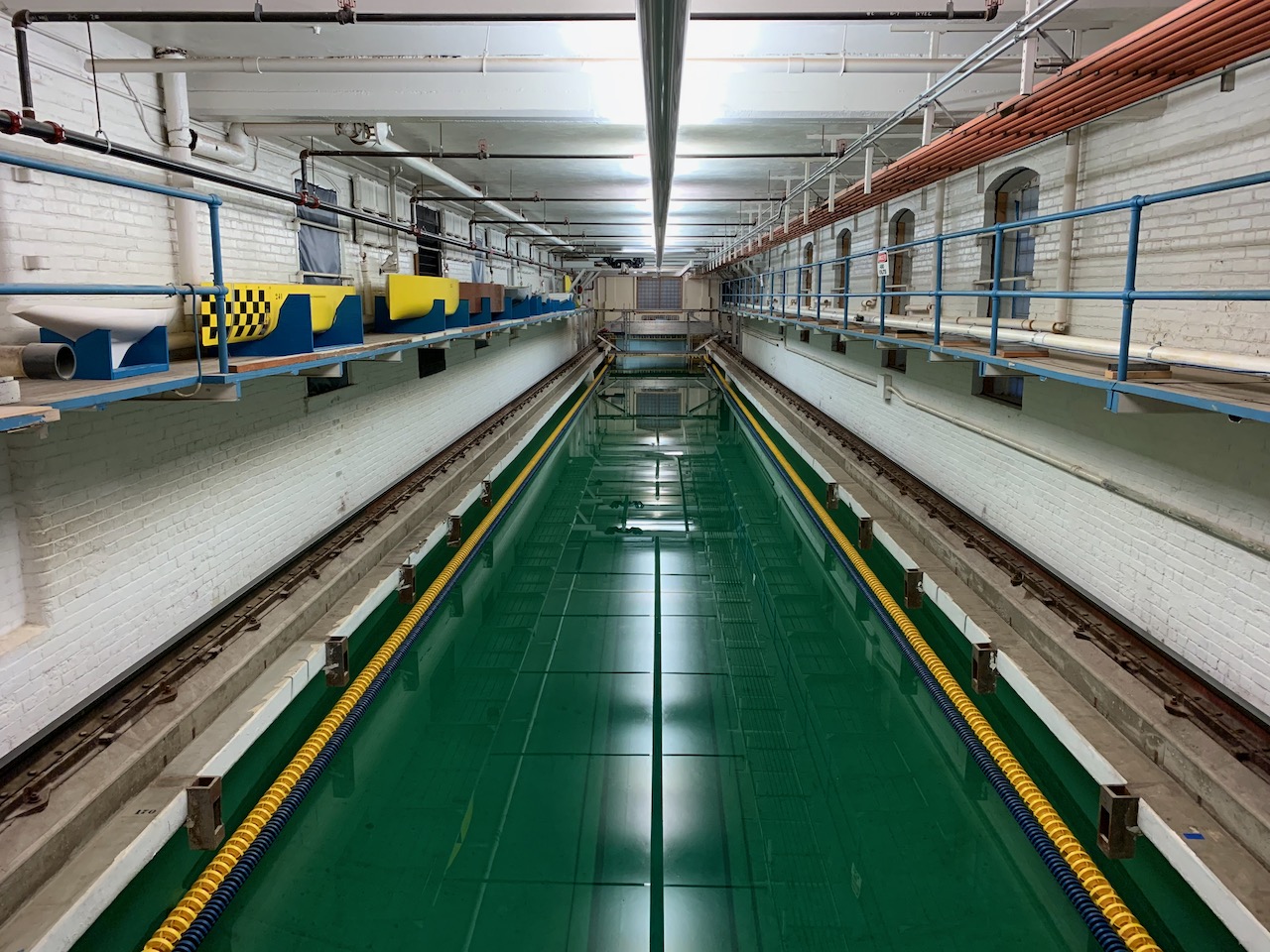
The Marine Hydrodynamics Laboratory (The MHL)
We will test our ROVs at the Aaron Friedman Marine Hydrodynamics Laboratory in West Hall on Central Campus.

The physical model basin (also called the towing tank) at the Aaron Friedman Marine Hydrodynamics Laboratory (MHL) was built in 1905, and it was the first towing tank owned and operated by an educational institution in the United States. Remodeling activities began during 1962 and continued in 1980 and 1990. Since 2001, the capabilities have been under continual upgrade and improvement.
The model basin is equipped to facilitate a full range of classical and innovative experimental procedures consisting of, but not limited to, the following:
- conventional ship resistance and propulsion testing
- advanced three-degree-of-freedom seakeeping tests
- flow-visualization using video and lasers
- three-component laser Doppler velocimetry
- directional stability, related to towing, using laser tracking
- maneuvering tests
The model basin is equipped with its own machine shop, model building facility, and electronics laboratory that are operated by skilled technical professionals. In addition to supporting the construction of accurate models of ships, barges, offshore structures, and specialized vehicles, platforms, and fixtures, this staff is responsible for providing and maintaining a full suite of model testing equipment that includes the following:
- ultrasonic and capacitance wave probes
- accelerometers
- rate gyroscopes
- a variety of computer controlled planar motions mechanisms
- string potentiometers
- LVDTs and RVDTs (non-contact instruments to measure displacement without friction effects)
- load cells
- pressure transducers
- flow meters
- custom-built equipment to facilitate specialized testing activities
In addition, the towing tank is equipped with an electrically driven computerized wedge-type wave maker that is capable of generating regular (wave periods between 0.5 and 2.5 seconds) and random wave patterns using empirical time records or direct computer input. The principal characteristics of the towing tank are summarized in Table.
| Item | Description |
| Drive system type and total power | Four 5kW brushless servo motors using computer control for optimum speed regulation |
| Tank length | 109.7 meters (360.0 feet) |
| Tank width | 6.7 meters (22 feet) |
| Tank depth (to edge of trough) | 3.05 meters (10.0 feet) |
| Typical water depth | 3.2 meters (10.5 feet) |
| Carriage type | Manned bridge and unmanned trailer |
| Carriage speed (min. and max.) | 0.08 to 6.10 m/s (0.25 to 20.0 ft/s) |
| Wave Maker type and class | wedge-type capable of generating regular and irregular waves; computer generated for any spectrum |
| Wave making parameters | Wave Period – 0.63 to 2.2 seconds Wave length – 0.61 to 7.62 meters (2.0 to 25.0 feet) Maximum wave height – 0.23 meters (0.75 feet) |
| Wind making capability | None |
| Run time cycle | Variable depending on the type of test and size of model (typically 15 minutes without waves and 30 minutes with waves) |
As the MHL is a working laboratory, it is an inherently dangerous place. Besides the power tools in the machine and model shops, the carriage that you will work on in the towing tank is powered via high voltage electricity lines.
The MHL is a marine laboratory, so there is the additional danger of water and slippery surfaces. Space and walkways can be tight around the existing equipment and temporary set-ups for different experiments. Therefore, it is vital that you observe all posted safety signs and the instructions of the lab technicians and your IA.
Pay close attention to the orientation tour so you are aware of the proper places to sit or stand during testing.
Scaling Your Prototype to a Full-Scale ROV
Scaling is an application of dimensional analysis. In the ROV project, you make a prototype that is smaller (and cheaper to make!) than what you would use in the real world. You can use your prototype to figure how the vehicle acts, whether it is stable, how fast it is, etc. and then “scale it up” to how big the real vehicle will be. The scaling applies to the size of the vehicle and the forces that act on the vehicle.
When someone uses the word scale it can mean different things. In this class, there are 3 different ways that you will scale your prototype to full scale:
- Geometry
- Buoyancy
- Speed & power
The scaling approaches you should use in this class are described in the following sections.
Geometry
When someone uses the term “geometric scaling” it means changing the geometry of an object by a certain factor. If we take the small cube shown on the left in Fig and triple its geometric scale, we get the larger cube shown on the right in Fig.
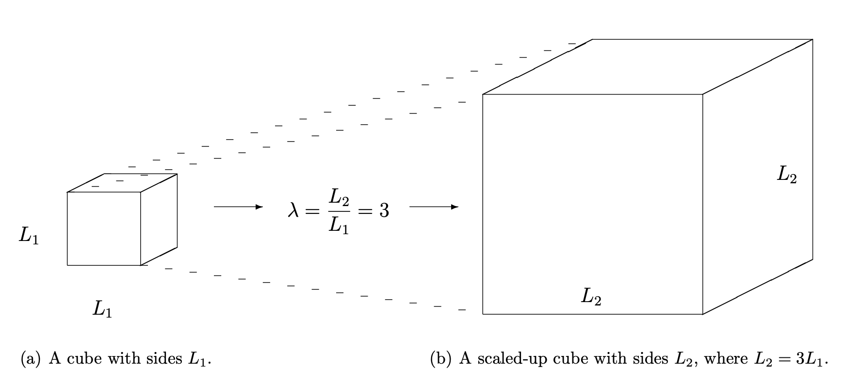
The initial cube has sides whose lengths are $L_1$, the scaled up cube has lengths whose sides are $L_2$, where $L_2 = \lambda L_1$. $\lambda$ is called the geometric scale factor and in this case, $\lambda = 3$. It is important to note that even though the geometry of the cube changes by the factor $\lambda$, not all properties of the cube are scaled in the same way. For example, compare the volume, $\nabla_1$, of the small cube in Fig with the volume, $\nabla_2$, of the large cube in Fig. It is straightforward to calculate these volumes:
\begin{equation} \nabla_1 = L_1^3 \end{equation}
\begin{equation} \nabla_2 = L_2^3 \end{equation}
Note that we can also write:
\begin{equation} \nabla_2 = L_2^3 = \left ( \lambda L_1 \right )^3 = \lambda^3 L_1^3 = \lambda^3 \nabla_1 \end{equation}
So, a length will scale as $\lambda$, but a volume scales as $\lambda^3$. Surfaces scale as $\lambda^2$. In the ROV project, you will be given a scale factor that you will then apply to your ROV because the client has specified this scale factor. Often, the choice of scale factor will be up to you.
Buoyancy
The overall buoyancy of your vehicle depends on its underwater volume. As mentioned in the section on buoyancy, a vehicle’s net buoyancy is the buoyancy minus the total weight:
\begin{equation} F_{b_{net}} = F_b - \Delta_{total} \end{equation}
If $F_{b_{net}}$ is small, the vehicle is said to be near-neutrally buoyant. This is an ideal condition for the ROV you will make in this course.
Once you scale the geometry of your ROV, you will have the full-scale volume of your vehicle. From this, you can calculate its buoyancy. The total weight will depend upon both the full-scale volume and your choice of materials.
Materials & Mass/Weight
To determine the CG of your vehicle, you will either apply (x,y,z) locations to your bill of materials and calculate the CG or you will have a computer program (e.g. Onshape) calculate your CG. In either case, the weight and CG of your vehicle depends on the densities of the materials you use. Your full scale vehicle will use different materials (which materials are your choice). Therefore, to calculate the full scale vehicle’s total mass, you need to use the same approach to calculate CG but with different material densities.
Effects of Water Density
You are testing the ROV in a test tank using fresh water. However, real marine vehicles must be able to operate in salt water as well. Freshwater and sea water have quite different properties. One of the major differences is density, as shown in Table.
| Temperature | Fresh Water | Salt Water | |
| °C | °F | $g/cm^3$ | $g/cm^3$ |
| 0 | 32 | 0.9998 | 1.0280 |
| 10 | 50 | 0.9996 | 1.0269 |
| 20 | 68 | 0.9981 | 1.0247 |
| 30 | 86 | 0.9957 | 1.0217 |
In general, fresh water is lighter than salt water. This factor will determine the difference between the buoyancy of a submersible operating in freshwater compared to saltwater. The buoyancy of a submersible in freshwater is:
\begin{equation} F_{b_{FW}} = \rho_{FW} g \nabla \end{equation}
The buoyancy of a submersible in saltwater is:
\begin{equation} F_{b_{SW}} = \rho_{SW} g \nabla \end{equation}
Assuming the volume, $\nabla$, remains the same, and the force of gravity, g, is the same, the ratio of salt water buoyancy to fresh water buoyancy is:
\begin{equation} \frac{F_{b_{SW}}}{F_{b_{FW}}} = \frac{\rho_{SW} g \nabla}{\rho_{FW} g \nabla} = \frac{\rho_{SW}}{\rho_{FW}} \end{equation}
In other words, the change in buoyancy is only due to the differences in the density.
Balancing Weight and Buoyancy
After you apply geometric scaling to your vehicle, apply the material choices, and calculate the buoyancy and weight of your full scale vehicle, it is very likely that the full scale buoyancy and weight will not result in a near-neutrally buoyant vehicle. Additional design iterations that look at changes in scale factor and material choices are necessary to achieve near-neutrality in full scale buoyancy. Achieving near-neutrality in buoyancy for the full-scale ROV is beyond the scope of this course.
Power, Velocity, and Thrust
As mentioned in the section on estimating the speed of your ROV, the drag of a vessel is proportional to the square of the velocity. The total drag, $D$, is assumed to be a function of:
- the cross-sectional area of the vessel ($A$)
- the velocity of the vessel ($V$)
- the density of the water ($\rho$)
- the kinematic viscosity of the water ($\nu$)
- gravity ($g$)
The scale ratio between a model ship and full scale ship is usually 30-60. This means that there are some significant differences in how the model ship moves through the water and how the full scale ship moves through the water, and we would need to address those differences in scaling power, velocity, and thrust by using a complicated 8-step calculation. Your full scale ROV has a scale ration of only 2.5. This means that your full scale ROV is more-or-less the same size as your “model” ROV (the one you’re building in this class), and we can use a somewhat simpler approach than what we use for ships.
To scale the power, velocity, and thrust from the ROV you built to the full scale ROV, you will:
- Calculate the actual coefficient of drag, $C_D$, of your ROV using experimental data
- Calculate the overall hydrodynamic efficiency, $\eta$, of your ROV
- Determine the full scale ROV’s power, velocity, and thrust based on $C_D$, $\eta$, and other requirements specific to the full scale ROV.
The next sections will explain how to do these scaling steps.
Calculating the Coefficient of Drag, $C_D$
When you go to the MHL, you will measure your ROV’s actual speed. Calculate its actual $C_D$ by rearranging Eq. \ref{eq:ROVTopSpeed}, the equation to estimate speed:
\begin{equation} C_D =\frac{T}{\frac{1}{2} \rho A_{ROV}V^2 } \label{eq:ActualCD} \end{equation}
where $T$ is the total thrust provided by your thrusters in the direction of travel, $\rho$ is water density, $A$ is the cross-sectional area of your ROV, and $V$ is the speed you measured at the MHL testing. $T$ is the same thrust you used for Eq. \ref{eq:ROVTopSpeed}.
In your final ROV report and presentation, you will need to compare your estimated $C_D$ with your calculated $C_D$ and comment on the difference between the two.
Calculating the Hydrodynamic Efficiency, $\eta$
Next, calculate the overall hydrodynamic efficiency, $\eta$, of your ROV. From the section on Propeller-Engine Matching:
\begin{equation} \eta = \frac{P_E}{P_{B}}\label{eq:EtaOverallDuplicate} \end{equation}
where your ROV’s effective power, $P_E$ is:
\begin{equation} P_E = D V = T V\label{eq:PEdefinition} \end{equation}
because drag equals thrust for our ROVs (there’s no throttle for the thrusters). The ROV payload system has a battery that provides 12 volts and can deliver 4.8 amps for 1 hour, so the brake power ($P_B$) for your ROV is
\begin{equation} P_B = V I = (12 \textrm{ volts}) (4.8 \textrm{ amps}) = 57.6 \textrm{ watts} \label{eq:PBdefinition} \end{equation}
Use this $P_B$ in Eq. \ref{eq:EtaOverallDuplicate} to calculate $\eta$.
Determining $P_B$, $V$, and $T$ for the Full Scale ROV
As mentioned above, your ROV is nearly the same size as the full scale ROV. Therefore, assume that $\eta$ for your full scale ROV is equal to $\eta$ for your ROV. For the full scale ROV, choose one of these methods to scale your brake power and velocity:
- Choose $P_B$ for the full scale ROV based on available batteries you could buy and justified with why you chose those batteries.
- Choose $V$ for the full scale ROV justify why you chose that speed for your ROV.
- Choose $T$ for the full scale ROV based on commercially available thrusters and justified with why you chose those thrusters.
Once you choose one of these values, you can determine the other two using your calculated $C_D$ and $\eta$ values, Eqs. \ref{eq:EtaOverallDuplicate} & \ref{eq:PEdefinition}, and this equation from the section on Propeller-Engine Matching:
\begin{equation} P_B \eta = \frac{1}{2} C_D \rho A V^3 \label{eq:CalcPBV} \end{equation}
It may take you several tries before you end up with a combination of $P_B$, $V$, and $T$ that your team is happy with; that’s okay! That’s part of the engineering design process.