ENGR 100-600 | University of Michigan
Statement of Work
Purpose
The purpose of document is to define the statement of work for the design and build of a prototype Remotely Operated Vehicle (ROV).
Project Background
LakePowerGen has won a government contract to build an offshore wind farm in Lake Michigan near Chicago, Illinois. The wind farm will need inspection ROVs to assist in the proper maintenance of the wind farm.
The proposed wind farm is designed around offshore wind turbines mounted on Tension Leg Platforms (TLPs) (see Fig).
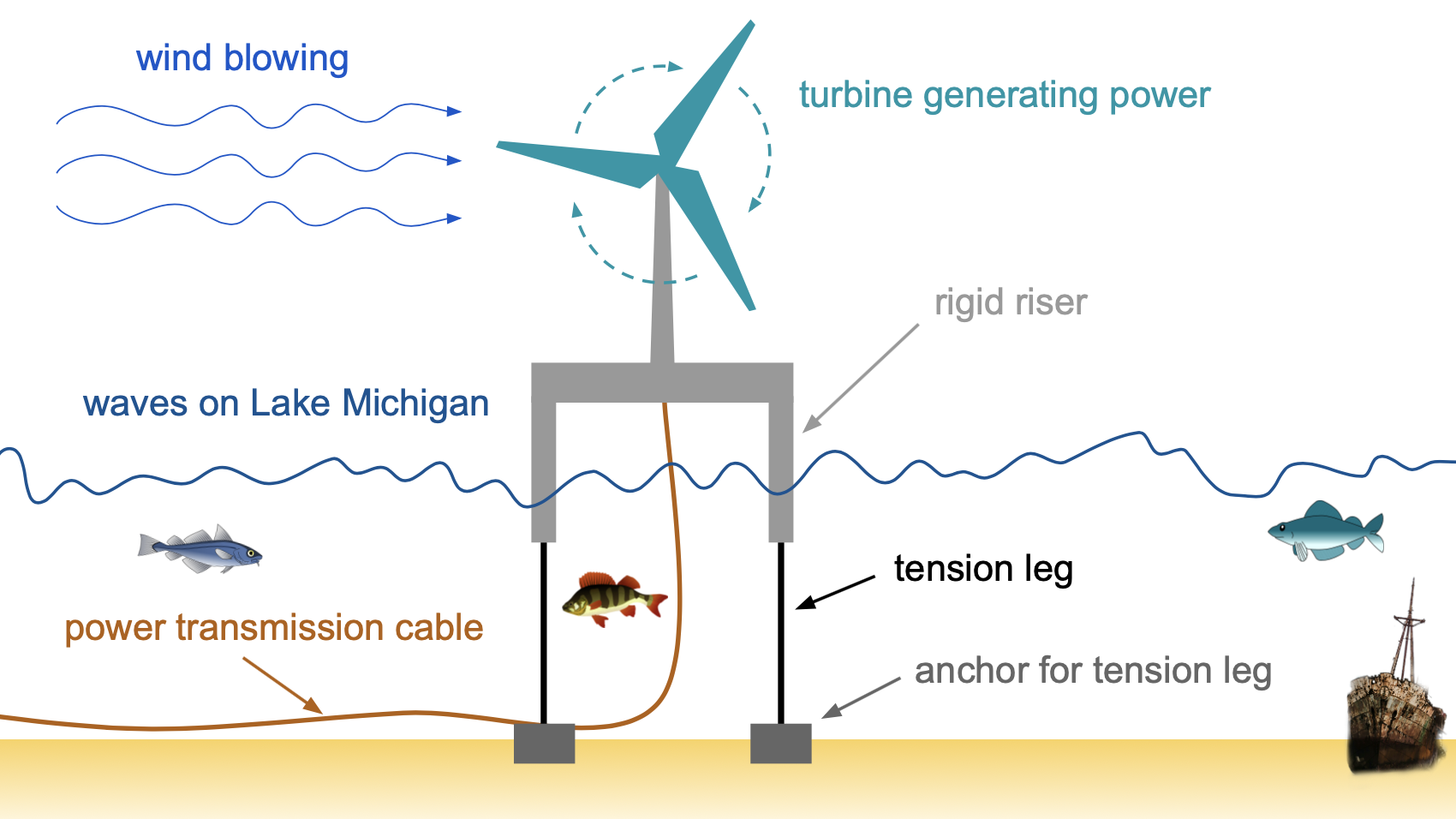
A major shortfall of typical ROV systems is their tether. The tether carries power and communication signals from the ROV to the support ship. However, the tether limits the maneuverability of the ROV. The inspection of the TLP risers, tethers, and undersea power transmission cable is particularly problematic as the tether can get wrapped around the risers, tethers, and cable. This causes delays in the inspection as operators must pause the inspection and backtrack the ROV to unwrap the tether from around the objects. Riser, tether, and cable inspection is critical to maintaining high efficiency power transmission from offshore wind farms to the mainland.
It would be most beneficial that a purposefully built, rapidly deployable ROV system be in place to allow for variances in offshore or working conditions. A highly maneuverable ROV that is able to efficiently inspect risers, tethers, and power transmission cables will increase the sustainability and profitability of offshore wind farms. Innovative solutions to these challenges are sought for possible future funding opportunities.
LakePowerGen Developed Semi-Tetherless Payload System
LakePowerGen has developed several prototypes of a semi-tetherless control system that uses wireless technology to mitigate the limitations of a fully-tethered ROV. A small antenna buoy is connected via a short tether to a payload system that is carried by an ROV. The payload system contains a battery canister that provides 12 volts and can deliver 4.8 amps for 1 hour. The battery canister is connected via a short cord to the electronics canister. The electronics canister supports the control of up to four (4) DC thrusters, a camera, a pressure sensor, and various other sensors. The antenna buoy is to be free-floating while connected to the ROV via the short tether. A wireless ROV controller connects to the antenna radio signal. The ROVs developed under this Statement of Work (SOW) must use this semi-tetherless control system. Because they are prototypes, each of the control systems are of slightly different weights. Each ROV must be prepared to use whichever control system it is given.
ROV Capabilities
Weekly, automated inspection of the TLP risers, tethers, and undersea power transmission cables will be performed by Autonomous Underwater Vehicles (AUVs), which quickly survey a large area of operation and flag equipment sectors that may have damage. Operators then use ROVs to go back to the flagged sectors and do a more careful, thorough inspection to determine what damage (if any) is present. The AUVs have an average false-positive rate of 1/20. The prototype ROV requested here will be used to inspect specific sectors of equipment that have already been flagged as potentially having damage. The ROV must enable the operator to efficiently find the correct sector, remain stable at the sector while the operator performs the visual inspection to verify and categorize the damage in real-time, and then move to the next sector without delays (e.g. from the tether becoming tangled). The ROV must be able to be transported by helicopter or service boat, and it must be able to be deployed by no more than two reasonably-abled people.
Terms and Definitions
| Term | Definition |
| TLP | Tension Leg Platform |
| ROV | Remotely Operated Vehicle |
| SOW | Statement of Work |
| VOR | Variation On Request |
| $L_{max}$ | maximum length |
| $W_{max}$ | maximum width |
| $H_{max}$ | maximum height |
| CG (LCG, TCG, VCG) |
center of gravity (longitudinal CG, transverse CG, vertical CG) |
| CB (LCB, TCB, VCB) |
center of buoyancy (longitudinal CG, transverse CG, vertical CG) |
| $\nabla$ | total underwater volume |
| $C_D$ | coefficient of drag |
| $A$ | cross-sectional area |
| $V$ | velocity (speed) |
| $T$ | thrust |
| $P_B$ | brake power |
| $\eta$ | hydrodynamic efficiency |
Statement of Work & Deliverables
LakePowerGen is requesting prototype design and construction of an ROV system. The Vendor is tasked with designing and building a prototype ROV system that meets requirements set out by LakePowerGen. The purpose of the ROV system will be to provide LakePowerGen with a lightweight, maneuverable, rapidly deployable system to meet Lake Michigan energy production needs. The Vendor is encouraged to develop several different designs in parallel in order to cover a wide range of potential solutions.
The ROV will carry a video camera by which a human operator will be able to guide the ROV. The camera, battery, and tether have already been manufactured as a subcomponent and will be a pre-packaged item that is the ROV’s payload. Because the ROV system must be easily carried by a human and must be easily transported by helicopter or service boat, controlling total mass is critical.
Throughout the development phase, the Vendor will perform periodic reviews of the Vendor’s internal design teams. At each review, the internal design teams will attend a meeting with their supervisors to discuss the chosen design and the work done to date. The Vendor will provide summaries of the reviews to LakePowerGen.
A final review and evaluation of all internal ROV designs will be organized and conducted by the Vendor and include the presence of LakePowerGen representatives.
ROV Prototype Requirements
The ROV prototype must:
- Not exceed a total system mass of 8.0 kg. This system mass includes all vehicle systems and components (including the payload and tether) but does not include water in the flood-able spaces. This will allow the system to be hand carried and helicopter deployable.
- Be slightly positively buoyant so that if the wireless connection is lost, the ROV will float to the surface to be retrieved.
- Be storable within the supplied rectangular enclosure measuring approximately 46cm x 32cm x 32cm high. The lid of the enclosure must be securely fastened with no "bulging" allowed. The ROV system can be manually deployed from this enclosure.
- Be able to go forward, backward, upward, downward, left, and right.
- Include station-keeping abilities so that an operator can use the ROV to perform a detailed visual inspection of undersea equipment
- Incorporate the following:
- A rigid body structure that
- has an attachment point for the ROV's tether's carabiner
- The attachment point should be on the top of the ROV so the tether can extend up to the float. The tether should be attached in such a way that the propellers are protected from entanglement with the tether, wires, seaweed, fishing nets, etc.
- has a quick attachment point for the camera
- is cemented together
- is floodable
- uses no more than 15 total feet of 1/2" PVC pipe
- has an attachment point for the ROV's tether's carabiner
- Clear line-of-sight for the video camera; the video camera must be protected from potential collisions (i.e., it can't be sticking out in front where it can crash into a wall)
- LakePowerGen-provided equipment:
- Payload — a cylindrical container for circuitry connected via a short cord to a separate cylindrical container containing the battery; payloads have slightly different weights but they are all positively buoyant
- Tether — neutrally buoyant
- Ability to change ballast weight quickly to account for different payload weights depending on which payload you are given
- Up to four 12V thrusters (motor and propeller combinations), which must
- be securely, but NOT permanently, attached to the ROV — the thrusters are to be recoverable for future projects
- be protected from bumps and collisions during transportation and operation
- protect propellers from entanglement with the tether, wires, seaweed, fishing nets, etc.
- Controller with switches and/or buttons, video display, antenna, and LCD display
Innovative Design
LakePowerGen is particularly interested in ROV designs that contribute to cutting-edge undersea technology. The Vendor’s ROV prototype must demonstrate a novel approach to ROV design in at least one area, including but not limited to:
- Different orientation of payload
- Different layout on controller
- Novel frame design
- Novel control/motion idea
- Improved efficiency
- Improved speed of mounting payload
- Improved ergonomics
- Improved robustness
Part of the purpose of this funded effort is to explore new areas of ROV design that can potentially lead to increased market share.
Approved ROV Materials
- 1 plastic box for controller
- toggle switches
- push buttons
- up to 4 thrusters (waterproof motor/propeller combinations)
- PVC pipe
- foam
- floats
- aluminum water bottles
- weights
- wire
- tether and controller connections
- zip ties
- bolts
- screws
- adhesives
- plastic netting
- other construction materials
NOTES:
- Duct tape may not be used for structural purposes.
- Designs that prioritize sustainability and limit one-time-use materials (such as zip ties) will be favorably reviewed.
- Other materials may be used with prior approval from management. Refer to VOR section for further details.
ROV Prototype Testing
The Vendor will perform preliminary testing of the ROV prototype at their own facilities. Testing will culminate in a formal showcase on Saturday, April 11, 2026, at the Marine Hydrodynamics Laboratory (MHL) during which teams will perform a simulated riser inspection task. Prior to the showcase, each team will have the opportunity to participate in testing at the MHL during the week of April 6 – April 10, 2026.
MHL Testing and Speed Measurement
During the testing at the MHL, each team will have the opportunity to test their ROV prototype in deep water, measure their ROV’s speed, qualitatively assess maneuverability, and practice with the showcase set-up.
Forward and/or backward speed will be determined by measuring the distance between the markers at the MHL, recording the time it takes for the ROV to travel along a straight-line path (under the water, but not at the bottom of the tank) between the markers, and dividing the distance by the time to determine top speed.
Upwards/downwards speed will be determined by measuring the distance from the bottom of the trench at the MHL to the water’s surface, recording the time it takes for the ROV to travel between the bottom of the trench to the water’s surface, and dividing the distance by the time to determine top speed. Note that ROVs must begin and end these tests in their normal “inspection attitude” (i.e., ROVs are not allowed to act like rockets, though they are allowed to rotate).
Lateral speed will be determined by measuring the distance between the sides of the tank at the MHL, recording the time it takes for the ROV to travel along a straight-line path (under the water, but not at the bottom of the tank) from one side to another, and dividing the distance by the time to determine top speed. Note that ROVs must begin and end these tests in their normal “inspection attitude” (i.e., ROVs are not allowed to travel in their “forward” direction across the tank, though they are allowed to rotate).
For any direction, the single run with the highest speed will be the team’s official speed in a given direction.
Showcase and Riser Inspection Task Description
At the showcase, each team will use their prototype ROV to simulate inspecting the risers of an offshore wind turbines. The inspection is non-destructive, non-contact.
As of the writing of this document, the steps in the simulation are as follows:
- Receive inspection sectors (e.g. 3A, 2E, 4C, …)
- Start timer
- Find sectors and note what damage (if any) to the riser is present in the sector. Examples of damage may include but are not limited to:
- Cracking
- Microbiological infestations
- Breakage
- Corrosion (general)
- Other material failure
- Joint failure
- Return to start line
- Stop time
- Compare damage report to the "correct" answers
- If damage report is correct, then that run is successful.
- If damage report is not correct, re-inspect the wrong sectors; continue until damage report is correct.
- When damage report is complete and correct, remove your ROV from the tank
NOTE: These showcase tasks are subject to change. If changes are necessary, you will be notified with a separate document.
A schematic of the showcase set up is shown in Fig.
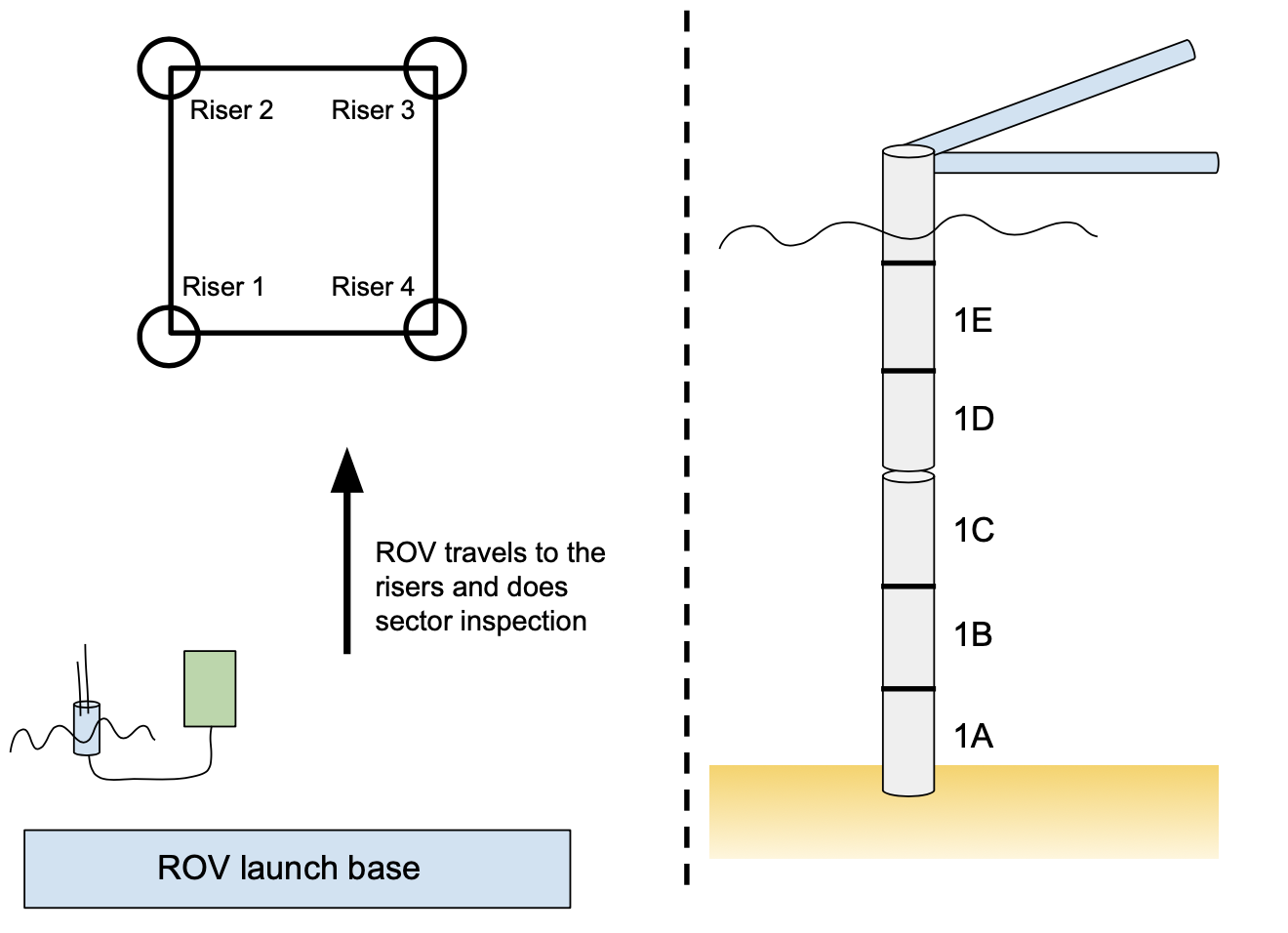
Each team must correctly complete the entire riser inspection simulation to have a qualifying run. Teams should explain how the prototype is specifically designed for the simulation, and how the ROV design in full scale meets LakePowerGen’s needs in the ROV progress report and final report and presentation.
Additional Information from LakePowerGen:
- A LakePowerGen representative will be available to interpret the specifications and rules and to make modifications if necessary.
- Additional information or changes may be forthcoming.
Full-Scale ROV Requirements
The prototype ROV will be used to inform design decisions for the full-scale ROV. (The creation of a full-scale ROV is not part of this Statement of Work). Criteria for the full-scale ROV are:
- Scale ratio of 2.5
- Scale payload size with ROV; mass of payload is undetermined as of the writing of this SOW
- Operational area is Lake Michigan
- Horizontal motion: minimum speed of 1.5 m/s greater than the lake current speed (usually still called “ocean current” in data sets)
- Vertical motion: minimum speed of 1.5 m/s
Vendors should provide recommendations for the design of a full-scale ROV based on the performance of the prototype ROV. Recommendations should include:
- Overall size
- Recommended weight allowance based on maximum buoyancy of the full-scale ROV
- Recommended guidelines on the arrangement of equipment on the ROV to maintain hydrostatic and hydrodynamic stability
- Performance parameters for 2-3 different directions of travel: speed, hydrodynamic efficiency, thrust required (include justification for all)
- Recommended materials, including for the ROV frame and subsystems (buoyancy, thrusters, battery, controller, etc.)
- Comments/recommendations on system reliability and ease of operation
- Any anticipated design changes to the prototype
Deliverables
LakePowerGen requests a copy of the Vendor’s Critical Design Review Presentation for each team’s proposed ROV design. Upon completion of prototype construction and testing, each team will prepare oral and written final reports detailing the design, construction, and performance of the ROV. Each team will also prepare a video documenting the innovation demonstrated by their ROV design.
These deliverables will be due according to the following table:
| Deliverable | Type | Due Date |
| Critical Design Review Presentation | Formal Presentation | 16 MAR 2026 |
| Final Presentation to Client | Formal presentation | 10 APR 2026 |
| Innovation Video | Video | 20 APR 2026 |
| Final Report to Executive Team | Formal Written Report | 22 APR 2026 |
These deliverables are described in more detail in the following sections.
Critical Design Review Presentation
The Critical Design Review Presentation is a 9-minute formal presentation that will include the following sections:
- introduction
- design scenario, including possible references to existing literature (i.e., scholarly journal papers)
- design goals/rationale
- design description
- design drawings/pictures of the ROV
- justification and description of the design, including possible references to existing literature (i.e., scholarly journal papers) and highlighting the innovation aspect of the ROV
- discussion of maneuverability
- preliminary bill of materials (simplified)
- preliminary stability analysis
- anticipated forward speed
- preliminary testing results
- estimated cost of construction
- project progress
- status of construction of component systems
- timeline for completion of ROV project
- distribution of team responsibilities, including assigned leads for major tasks and deliverables
- conclusions and recommendations
Final Presentation to Client
The Final Presentation to Client is a 15-minute formal presentation that will include the following sections:
- introduction
- design scenario
- goals/rationale
- design description
- design scenario, including possible references to existing literature (i.e., scholarly journal papers)
- design goals/rationale
- design description
- design drawings/pictures of the ROV
- justification and description of the design and highlighting the innovation aspect of the ROV
- bill of materials (simplified)
- stability analysis
- performance
- preliminary test data
- anticipated forward speed vs. measured forward speed recorded at MHL; comment on the comparison
- preliminary maneuverability at GFL and maneuverability during testing at MHL
- ability to go forward, backwards, left, right, up, down
- ease of operation
- preliminary results of ability to perform riser inspection
- analysis of performance parameters
- table of principal particulars for the prototype; see Appendix
- information required for full-scale operation in Lake Michigan, including a table of principal particulars for both the prototype and full scale.
- The table of principal particulars is split into two parts (geometry and performance) and should include a column for the prototype values, a column for the scaling method, and a column for the full scale values.
- Include a scaling analysis for forward surge and heave, either up or down.
- The tables in the Appendix show what we are looking for at a minimum in the tables of principal particulars.
- conclusions and recommendations
Innovation Video
We expect the innovation videos to be relatively short (< 4 minutes); they will highlight the overall innovation of the ROV for an audience of venture capitalists. Your video should detail specific innovations and their role in your ROV system with particular focus on the improvement to performance (or another relevant metric, such as safety or cost).
Each video will need to be accompanied by production materials such as scripts, post-production notes, and a list of credits. Further details, including minimum production requirements, are forthcoming separately.
Final Report to Executive Team
We expect the Final Report to the Executive Team to be approximately 12-20 pages. It will be in the form of a formal written report (including title page and executive summary) and will include the following sections at a minimum:
- title page
- table of contents
- executive summary
- introduction
- design scenario, including possible references to existing literature (i.e., scholarly journal papers)
- design goals/rationale
- design description
- design drawings/pictures of the ROV
- justification and description of the design, including possible references to existing literature (scholarly journal papers) and highlighting the innovation aspect of the ROV
- bill of materials (detailed)
- stability analysis
- performance
- preliminary test data
- anticipated forward speed vs. measured forward speed recorded at MHL
- preliminary maneuverability vs. maneuverability during showcase
- ability to go forward, backwards, left, right, up, down
- ease of operation
- results of riser inspection simulation at showcase
- analysis of performance parameters
- table of principal particulars for the prototype; see Appendix
- information required for full-scale operation in Lake Michigan, including table of principal particulars (see Appendix for the form of these tables)
- conclusions and recommendations
- references
- appendices (if needed)
Submission
Deliverables sent via email or submitted in paper form will NOT be accepted.
Critical Design Presentation Slides — Presentation slides must be submitted via Canvas in .pdf format no later than 11:59pm on Monday, March 16, 2026.
Final Presentation to Client — Presentation slides must be submitted via Canvas in .pdf format no later than 11:59pm on Friday, April 10, 2026.
Innovation Video — Upload the final version of your Innovation Video to YouTube and mark it as “unlisted.” Submit a .pdf of your supplementary materials (include the link to the video) to Canvas no later than 11:59 pm on Monday, April 20, 2026.
Final Report to Executive Team — The written report must be submitted via Canvas in .pdf format no later than 11:59 pm on Wednesday, April 22, 2026.
VORs in General
Individual VORs shall be issued for individual items that require component and labor cost beyond this initial deliverable list.
Any additional materials requested must be pre-approved by Dr. Alford and not exceed 20 USD. In order to minimize schedule disruptions, LakePowerGen requests that the equipment be field-ready as soon as possible, that work continue so long as Vendor and LakePowerGen agree to an individual or set of technical courses of action, that personnel, supplies and/or other equipment resources are available, that work may continue safely, and that LakePowerGen agrees in good faith to reasonable charges/costs from Vendor.
Omission by LakePowerGen/Vendor
At any time, if there is a question regarding the intent or extent of this document, the contract between LakePowerGen and the Vendor has precedence. If the contract does not give specific guidance on a given matter and this document does not directly address it, then it is a matter of omission and the document either requires revision and the quote updated or both parties agree to a subsequent VOR to address the error or omission.
This portion of the document extends to Vendor quality notices, engineering issues and other matters which other customers/users have developed, initiated, paid for (in part or in whole) which impacts directly or indirectly equipment used/rented by, sold to or otherwise held by LakePowerGen. Included in this: change notices, updates, and the like.
ROV Evaluation
ROVs will be evaluated and ranked in three categories:
- Maneuvering (as demonstrated at the showcase)
- Innovation
- Cost
The top-ranked team in each category will be awarded extra credit points on the final report. In addition, the overall feasibility of each design will be determined based on these three categories (see the Section on Overall Feasibility for details). The top-ranked team in overall feasibility will be awarded additional extra credit points.
Maneuvering
The official maneuvering evaluation of the Vendor’s ROVs will be done during the showcase. Maneuvering will be evaluated as the time it takes the ROV to correctly complete the riser inspection simulation. Teams must have correctly completed the riser inspection simulation to qualify for this category. Qualifying teams will be ranked according to time with 1 being the shortest, 2 being second shortest, and so on.
Innovation
The innovation of the team’s final design will be evaluated by a team of experts (the course instructional staff plus an industry expert). Teams should highlight their innovations in the Final Presentation to Client. Qualifying teams will be ranked according to the overall innovation of the ROV, including controls, frame design, buoyancy, etc. with 1 being the most innovative, 2 being second most innovative, and so on.
Cost
The cost of the team’s ROV will be verified and recorded at the showcase. Teams will bring a Bill of Materials to the testing that lists the individual cost of each part listed in the bill of materials along with a total ROV cost. Teams will be provided with an official cost list for all parts provided by LakePowerGen. These official costs must be used in the Bill of Materials. Teams must submit a correct Bill of Materials prior to the showcase to qualify for this category. After the team completes the showcase, they will bring their ROV and Bill of Materials to the Audit Station. Failure to bring a correct and accurate Bill of Materials will result in disqualification for this category. Qualifying teams will be ranked according to the total cost of their ROV with 1 being the least expensive, 2 being second least expensive, and so on.
Overall Feasibility
The overall feasibility of the team’s ROV will be evaluated by calculating a feasibility index for each ROV. The feasibility index is a weighted average of the three criteria:
- Maneuvering (as demonstrated at the showcase) — weight = 0.60
- Innovation — weight = 0.25
- Cost — weight = 0.15
In other words,
\begin{equation} \textrm{feasibility index} = \textrm{maneuvering rank} \times 0.60 + \textrm{innovation rank} \times 0.25 + \textrm{cost rank} \times 0.15 \label{eq:feasibility} \end{equation}
Qualifying teams must have a ranking for each of the three categories above. Qualifying teams will be ranked according to their feasibility index (Eq. \ref{eq:feasibility}) with 1 being the lowest feasibility index, 2 being second lowest, and so on.
Contact List
| Name | Company | Position | |
| Laura Alford | Global Flotation Laboratories, Inc. | Partner | lslavice@umich.edu |
| Robin Fowler | Global Flotation Laboratories, Inc. | Partner | rootsr@umich.edu |
| Ella Alhudithi | Global Flotation Laboratories, Inc. | Partner | alella@umich.edu |
Appendix
Tables of Principal Particulars
All deliverables should include a table of principal particulars to summarize the ROV system.
For the prototype ROV, include this table of principal particulars:
| Property | Surge Forward | Heave Up (or Down) |
|---|---|---|
| $C_D$ | X.XX | X.XX |
| $A$ | X.XX units | X.XX units |
| $V$ | X.XX units | X.XX units |
| $T$ | X.XX units | X.XX units |
| $P_B$ | X.XX units | X.XX units |
| $\eta$ | X.XX | X.XX |
For the full-scale ROV, a summary table of the geometric scaling should be included:
| Property | Prototype | Scaling Method | Full Scale |
|---|---|---|---|
| $L_{max}$ | X.XX units | description | X.XX units |
| $W_{max}$ | X.XX units | description | X.XX units |
| $H_{max}$ | X.XX units | description | X.XX units |
| CG (LCG, TCG, VCG) | X.XX units | description | X.XX units |
| CB (LCB, TCB, VCB) | X.XX units | description | X.XX units |
| $\Delta$ | X.XX units | description | X.XX units |
| $\nabla$ | X.XX units | description | X.XX units |
The full-scale ROV’s performance should be summarized using the tables below. Note: heave should be reported as either heave up or heave down, but not both.
| Surge Forwards | |||
|---|---|---|---|
| Property | Prototype | Scaling Method | Full Scale |
| $C_D$ | X.XX | description | X.XX |
| $A$ | X.XX units | description | X.XX units |
| $V$ | X.XX units | description | X.XX units |
| $T$ | X.XX units | description | X.XX units |
| $P_B$ | X.XX units | description | X.XX units |
| $\eta$ | X.XX | description | X.XX |
| Heave Up (or Down) | |||
|---|---|---|---|
| Property | Prototype | Scaling Method | Full Scale |
| $C_D$ | X.XX | description | X.XX |
| $A$ | X.XX units | description | X.XX units |
| $V$ | X.XX units | description | X.XX units |
| $T$ | X.XX units | description | X.XX units |
| $P_B$ | X.XX units | description | X.XX units |
| $\eta$ | X.XX | description | X.XX |