ENGR 100-600 | University of Michigan
ROV Controller Assembly
Step-by-Step Instructions for Assembly of a Wireless Remote ROV Controller – ENGR 100-600
Last updated: Fall 2025
Background
The ROV is controlled by the ROV payload which receives commands from the ROV controller. We have communal ROV payloads that are shared by all the class teams. The payloads are custom-built packages that are extremely valuable, so please handle them with great care. The ROV controller is built by you! Despite its simple looks, even the controller you build is worth about $70 in components and lots of your time.
It will be tempting to skip right to the section of these instructions that covers building the controller so that you can make immediate apparent progress. However, it is strongly recommended that you spend a few minutes reading through this whole instruction set. That will ensure that you are familiar with what you are making, and will give you a sense of what all has to be done. It is much better to be mentally prepared for the later steps of the construction process than to get to them and realize that you need to move a component or rewire something because you didn’t know what was coming next. If anything is unclear, don’t guess; ask questions!
Tip for Success
It should be stated right from the beginning that electronics work does not admit guessing. If your wiring does not work, DO NOT just begin swapping wires around hoping that this might fix it. You must know what you are doing before you do it.
You will have some flexibility with your controls, but when it comes to the electronic components, there is no flexibility. Each wire must go exactly where it is supposed to, or your box will not work and you will probably also destroy some of the electronic components.
This controller project is the time to channel your most meticulous state of mind and be tidy and exacting to the highest degree you can. Fortunately, you do not need to know anything about electronics to be successful. You just need to carefully follow this guide and you will get it right.
ROV Payload Overview
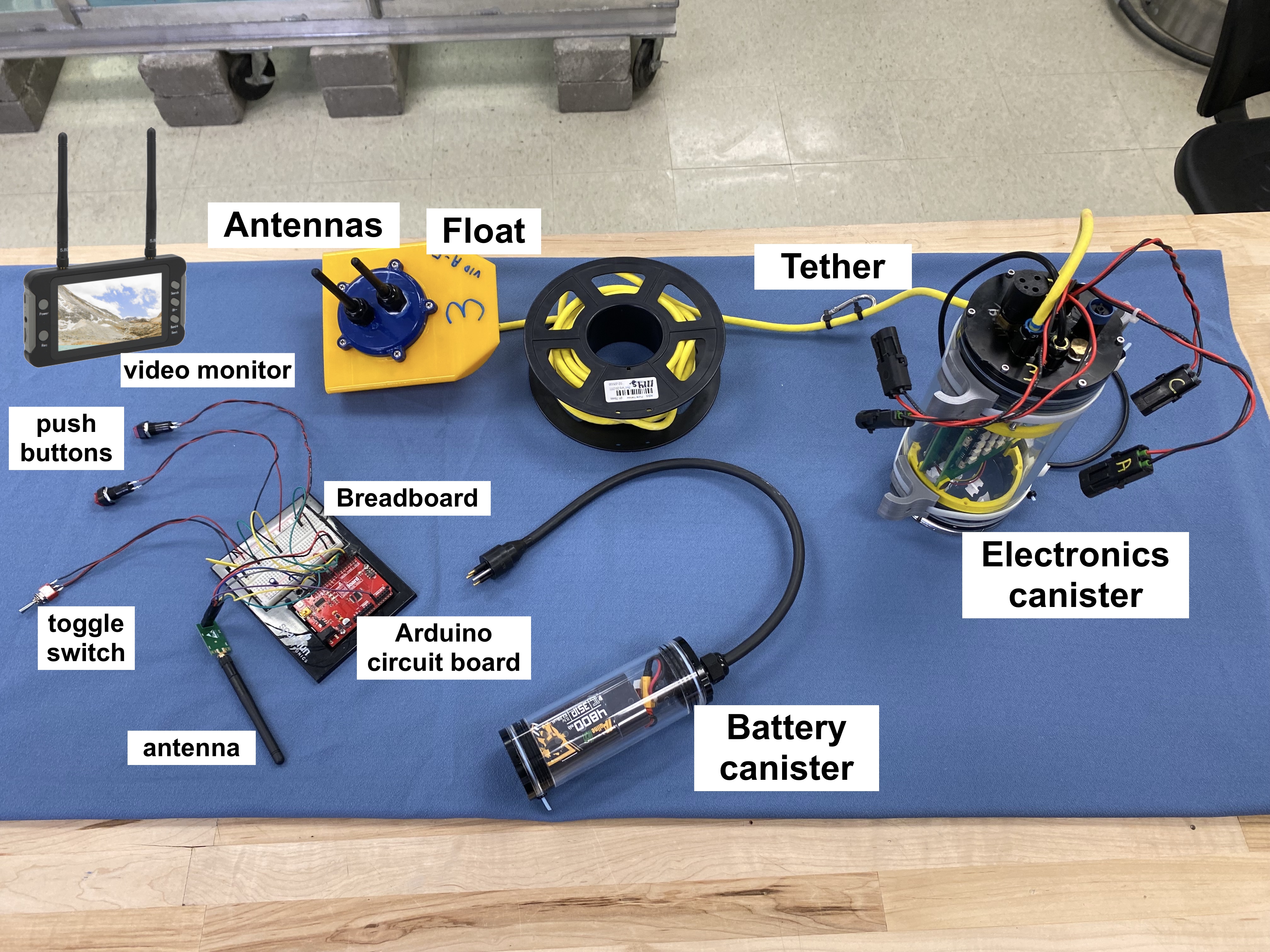
The ROV payload system is shown in Fig. The payload itself is the clear plastic cylinder with the electronics inside. A yellow, neutrally buoyant tether cable connects the payload cylinder to a plastic antenna buoy-boat that floats on the surface of the water. The antenna boat allows the wireless signals to pass back and forth to your controller and down to the ROV payload cylinder, because the water would otherwise block the signal. Your controller will have buttons and/or switches that are connected to an Arduino. Your commands go from the buttons to the Arduino and then to your controller’s antenna and then are sent to the antenna buoy-boat.
ROV Payload Theory of Operation
The ROV is maneuvered in the water by 4 constant (single) speed reversible thrusters. A payload is installed on the ROV that controls the thrusters and carries a video camera to carry out its function as a mobile underwater inspection device. The payload also has some instrumentation that sends data back to the operator about the ROV’s operating status. Power to the payload is provided by a 4.8 Ah 3S lithium ion battery in an independently detachable submersible compartment. The payload is also capable of operating up to two submersible servo motors. (Currently, the payloads are only set up to operate one servo.) The payload is sealed and need not (and should not!) be opened under normal circumstances. Do not attempt to open the payload.
The ROV has two radio links: a two way link at 2.4 gHz that passes thruster control and payload instrumentation data, and a one-way link at 5.8 gHz that transmits the video. This allows the ROV to operate without a hard wire tether linking it to the shore/operator. However, since high frequency radio cannot be sent through water, the ROV must tow a buoy which is tethered to the surface above it that carries the radio transmitters. The depth of operation of the ROV is thus limited by the length of the tether to its transmitter buoy, in our case about 25 feet, but it is otherwise free to roam as far as the range of the radios, subject to keeping an open surface above itself it so the tether to the surface does not get tangled. The 5.8 gHz radios with simple antennae are good out to a few hundred feet as long as unobstructed line of sight is maintained. The 2.4gHz control radio has selectable power levels with maximum range greater than 1 km.
ROV Payload Components
The payload’s internal components comprise:
- An Arduino “Micro” microcomputer
- Motor control switching circuitry using 16 solid state relays.
- A Bosch BNO 055 inertial measurement unit (IMU)
- A Pololu ACS724 current measurement sub board
- An Adafruit DS3231 real time clock
- A pressure transducer
- A conductivity probe
These components reside on two custom fabricated printed circuit boards inside the ROV casing.
The payload permanently attaches an external submersible video camera with LED lighting.
The surface buoy carries:
- A Pololu AStar 32U4 Arduino
- A 5.8 gHz video transmitter
- An nRF24L01 2.4gHz transceiver
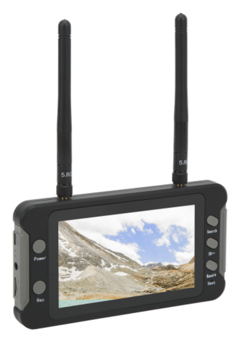
Communication between the payload Arduino and buoy Arduino is via serial link. The AStar 32U4 in turn talks to the nRF24L01 via SPI protocol (a short distance protocol). The video signal to the 5.8 gHz transmitter is a direct passthrough of the camera output. The video receiver unit (Fig) is self contained and independent of the ROV controller. It has an internal rechargeable battery and can capture received video to an SD card.
Log Data Sent FROM the Payload
Payload instrumentation sends the following data packet to the ROV controller once per second:
- Pitch, roll, and yaw data from the IMU. The zero yaw value is fixed each time the payload is powered up. Whatever direction it is facing when powered will be 0 yaw.
- Timestamp. ROV clocks are set to Universal time so they will be 5 hours ahead of Ann Arbor local time (4 hrs during DST).
- Pressure in cm of depth in the water.
- Battery voltage.
- Instantaneous current draw.
- Ambient temperature.
- Conductivity probe reading. This functions as a leak detector for the payload. Conductivity will read near zero if the probe remains dry. If enough water enters the payload to wet the probe, conductivity will rise to some number between roughly 50 and 300 depending on the ambient water quality.
If you ever see a conductivity reading, GET YOUR ROV OUT OF THE WATER IMMEDIATELY! There is a leak in the payload!
Control Data Sent TO the Payload
To control the payload, six numbers must be set by the ROV Controller:
- 4 bytes that contain either a 0, 1, or 2. The values correspond to the state of each of the four thrusters: off, on, or reverse respectively.
- 2 bytes containing an angle from 0-180° to control servo positions. These need not be set if servos are not in use.
ROV Controller Overview
The ROV controller is what you will use to “drive” your ROV; the controller sends the control data described above. The controller will include the buttons and switches that your use to control the thrusters as well as a video monitor and LCD display. A sample controller is shown in Fig.
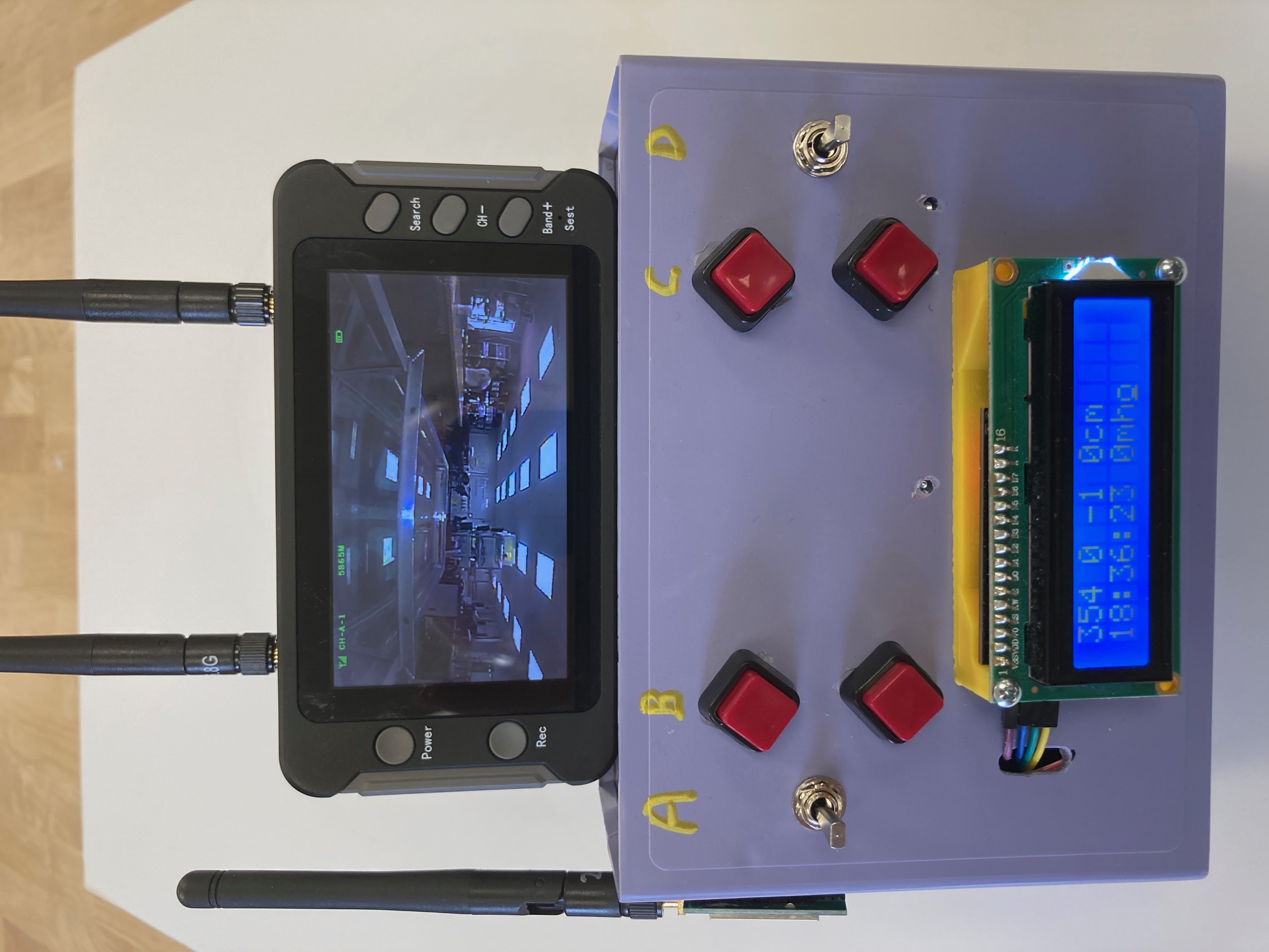
The design of the controller is completely up to your team. This document describes how to make this sample controller. You may adapt these instructions in whatever way you need for your own controller.
ROV Controller Theory of Operation
The controller comprises the following components:
- Case
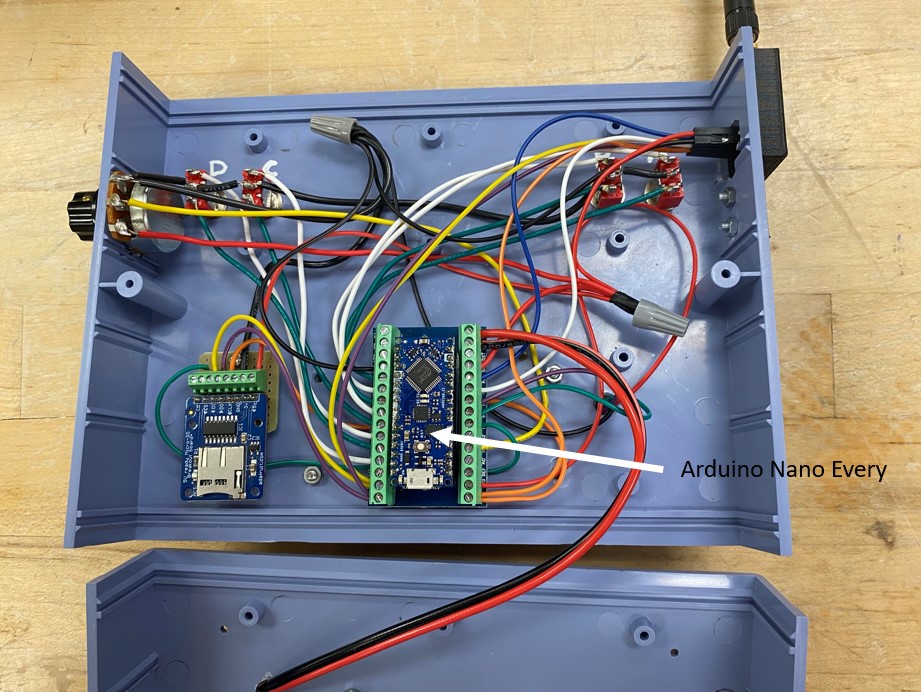
- Arduino Nano Every microcomputer with wiring shield
- 16 x 2 character LCD display
- SD card writer
- nRF24L01 radio
- Manual control input devices: switches and potentiometers
As in the buoy, the Arduino communicates to the nRF24L01 via SPI. It also talks to the SD card writer via SPI, which allows multiple devices to be on the SPI bus in parallel. Communication to the LCD display is via I2C protocol.
Any battery between approx 6.5 - 12 V can be used to power the controller. We have rechargeable 2S lithium ion and lithium iron phosphate packs available for powering controllers.
Insertion of an SC card to the controller writer is optional. However if one is present, all data received from the payload will be logged to a .csv file on the card.
Programming the ROV Control System
Since payloads are shared by teams they must present a consistent interface, thus payload (and buoy) programming is fixed and may not be modified by users.
The payload Arduino operates at roughly 10 cycles per second. On each cycle, it reads the onboard instruments, loads the data into a packet for the nRF24L01 radio and sends the packet up a serial link to the Arduino in the buoy. As soon as the buoy has a packet it sends it off to the nRF24L01 for transmission. The pair of nRF24L01 radios in the buoy and controller implement an automatic response system, so as soon as the controller receives payload data it responds by sending back the current control data.
When the return packet arrives at the buoy, it sends the data as serial data down to the payload. The payload Arduino reads it, sets the states for the motors and servos, and starts the execution of the next loop. All synchronization is driven by the payload controller; the other components in the system just wait for it to initiate and then respond. Each payload is numbered and a controller is paired to a payload by entering that number in the controller Arduino code, recompiling and uploading it to the controller.
ROV Controller Logic
You will be provided with a computer program that has a basic control scheme for the thrusters and servo already set up. If you would like to implement custom code, or just want to understand the program better, these next sections give detail on the logic required for controlling the thrusters and servo.
Thruster Control
The controller will respond to the payload automatically each time it receives a packet from the payload, so all the controller has to do is keep its output data buffer up to date and it will get sent on schedule.
As noted above, the controller reads the position of a set of thruster control switches and loads data representing those states into the 4 control bytes to be sent to the payload. The stock Arduino code provided implements default logic for doing this based on the use of either one toggle switch or two push buttons for each thruster. In the case of a toggle, pushing one way will be forward, pushing the other will be reverse, and the neutral position is off. For two push buttons, one will actuate forward and one will actuate reverse.
Since each team builds its own controller, teams are free to build and program their controller motor logic for any control scheme they can conceive, as long as in the end the Arduino sends a 0, 1, or 2 to the payload for each motor and as long as their combination of input devices doesn’t require more than 10 input lines on the Arduino (that is all that are available).
Servo Control
There are two simple ways to control a servo:
-
Connect a 10KΩ potentiometer to the arduino with the outer leads going to 5V and ground and the center signal lead connected to A0 or A1 on the Arduino. Map the analog reading of 0-254 into an angle of 0-180° and send that to the payload. The servo will rotate in synchrony with the potentiometer knob. This scheme is implemented in the default programming supplied.
-
Use two push buttons: push one and have the servo angle increase, push another for it to decrease, possibly a third button to reset it to its home position. If you want to implement this scheme and can’t figure out how, talk to a peer mentor, I/A, or instructor.
Building the ROV Controller
Your ROV is operated using a controller that your team will build from scratch. These instructions walk you through building a standard controller. Most teams vary from these instructions when it comes to the combination and placement of buttons, switches and potentiometers.
As mentioned at the beginning, please read all the way through these instructions BEFORE you start drilling holes and connecting components. This will be a bit like cooking, where it helps to read the recipe before you start so you know what is coming up next, and what has to happen at what stage. This will save you grief later.
1. Planning Your Arrangement
You are at the mockup phase of this project. You should have collected your box and components and have them all laid out in front of you. Chat with your group about how you want your controller to be set up. Here are some questions to ask yourselves:
- Do you want all the controls on the front panel?
- Do you want buttons on the back?
- Can people with both big and small hands use the controller?
- Did you position the Arduino and the SD card holder where they can be easily accessed when the box is closed?
You can look at the example controllers to get ideas on how to arrange the different components of your controller.
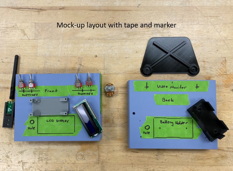
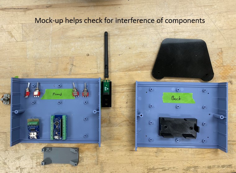
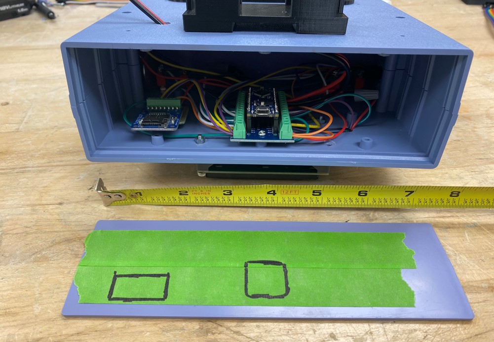
Put pieces of masking tape on your box to represent buttons and displays and other components (see example in Fig and (#SampleControllerMockupInside)). This simple mockup will allow you to see if your layout is reasonable, and will also help you to see if components will interfere with each other or with features in the box. For instance, you don’t want a button too close to the edge of the box because you might not be able to get the lock nut threaded on it. Or you might realize that the screws and nuts that hold the display on the front panel will interfere with the components inside the box like the Arduino breakout board. You might notice that placing the Arduino breakout board too close to another component will make it extremely difficult to wire it. You may have to work around or remove mounting bosses on the interior of the case if they interfere with your plans. A little time spent in the planning and mockup phase will pay dividends later by avoiding annoying mis-drilled holes and interfering components. You only get one box, so plan wisely!
2. Creating Holes in Your Box
STOP! Look over your design with Justin or IA before cutting and drilling. You only get one box!
Once you have decided where all your components should be located to meet your functional, aesthetic, ergonomic and interference requirements, you need to drill and cut holes in your controller. You have several options for creating holes in your boxes. You can drill holes, you can saw holes or you can mill holes with a Dremel.
Tip for Success
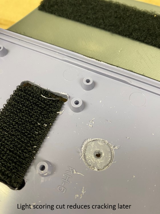
The plastic used in your box is relatively brittle and will crack easily. When drilling, there is more risk of cracking the plastic when using larger bits, and when drilling the plastic unsupported. Follow the procedures below to successfully put holes in the box.
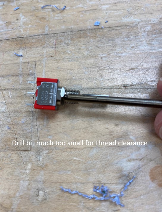
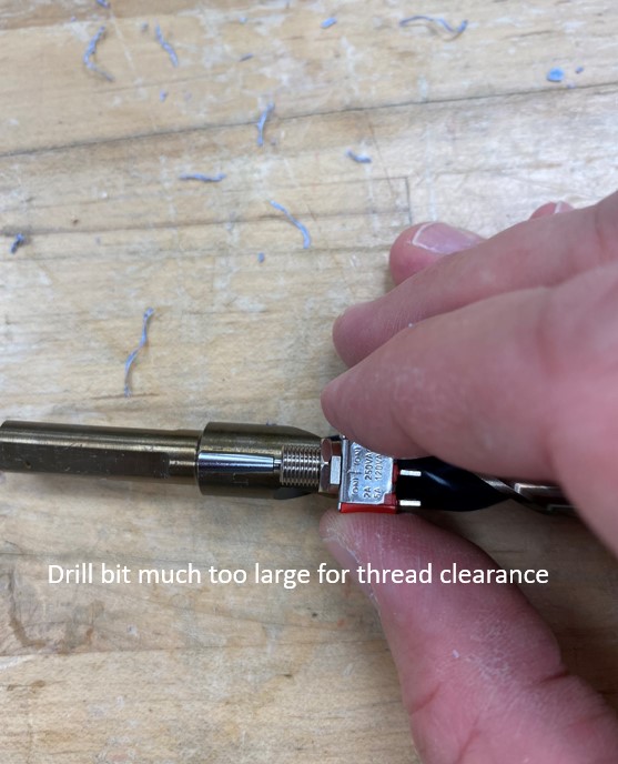
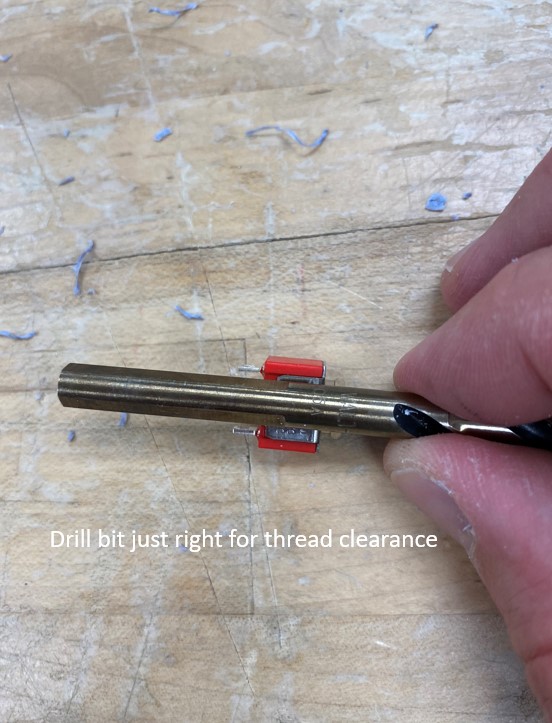
To select a bit, simply hold a reasonable bit in front of the item you need to drill for and confirm that it is just slightly bigger than the thing you need to put through the hole. To see what we mean, look at the following series of figures:
Example: Drilling 1/2-inch Holes for Push Buttons
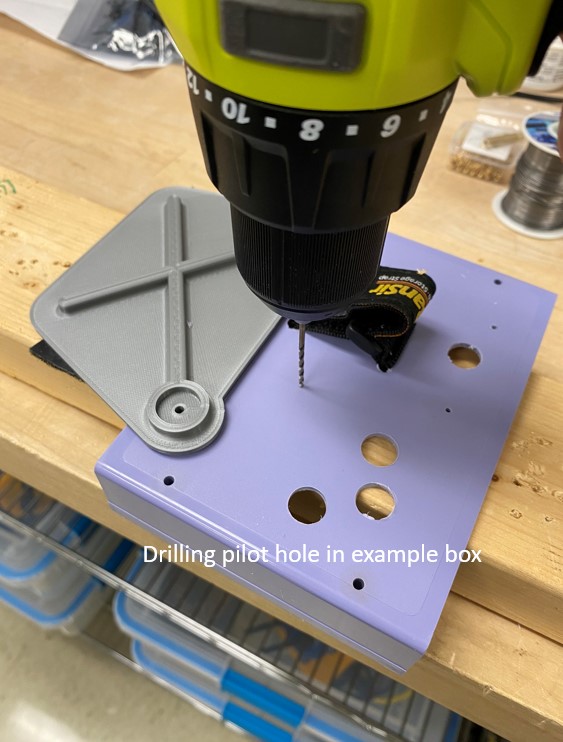
To drill the larger 1/2-inch holes for the push buttons, the following procedure is recommended:
- Get a piece of scrap wood to place beneath the plastic, to support the plastic and prevent damage to the workbench. Obtain the 1/2-inch Forstner bit (ask Justin for this bit).
-
Drill a small pilot hole for the larger bit to follow.
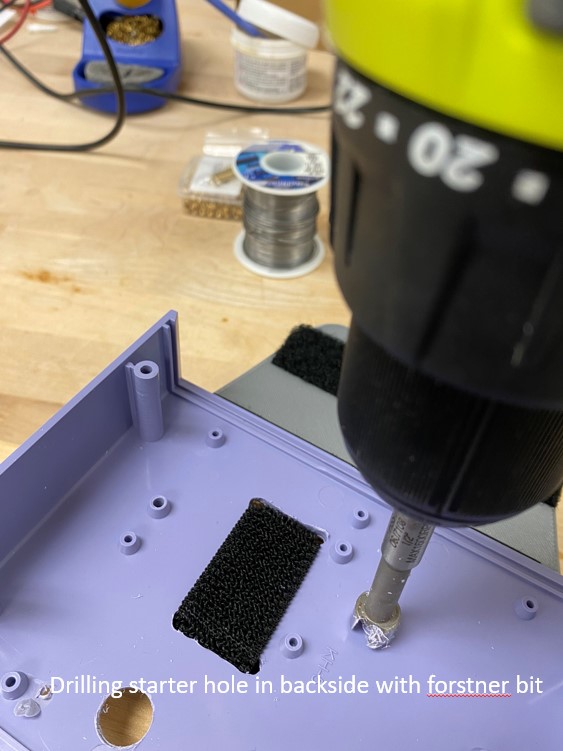
-
Drill a very shallow partial hole from the inside of the box first; this reduces the chances of the plastic blowing out on the surface.
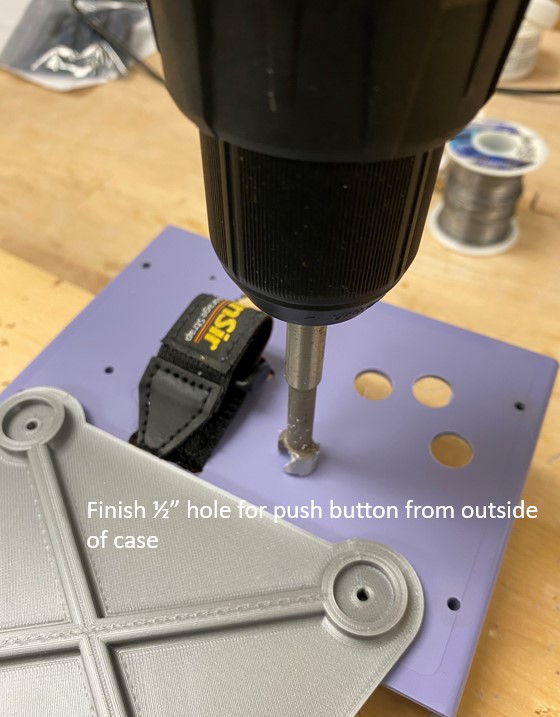
-
Finish drilling from the outside of the box. Press gently to reduce the chances of chipping and cracks.
Example: Drilling a Small Hole (up to ~1/4-inch)
To drill a small hole (up to about 1/4-inch), the following procedure is recommended:
- Get a piece of scrap wood to place beneath the plastic, to support the plastic and prevent damage to the workbench.
- Drill firmly but gently through the plastic into the support wood.
Example: Making a Hole of Arbitrary Shape with the Jigsaw
To saw a hole of arbitrary shape in your box with the jigsaw, the following procedure is recommended:
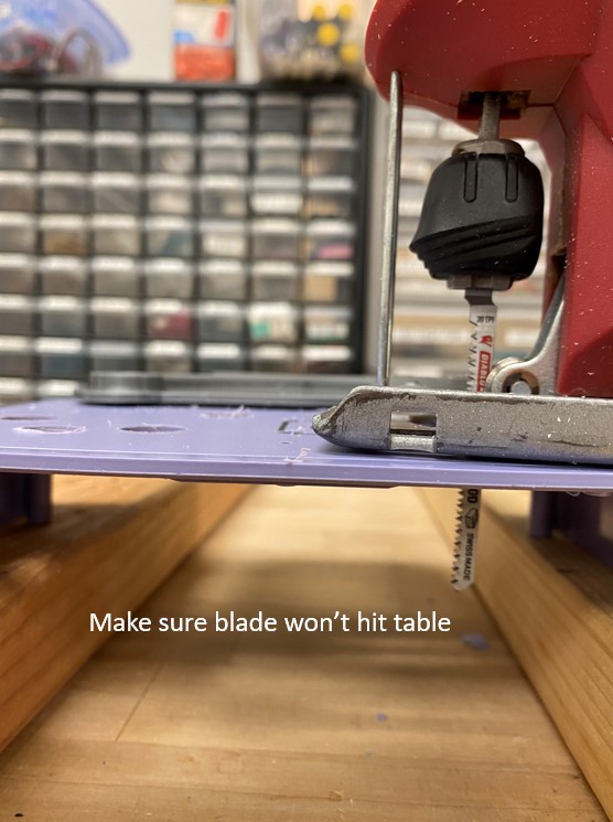
- Draw the outline of your cut on the box.
- Obtain scrap wood that can lift the plastic high enough above the bench that the jigsaw blade will not hit the bench.
-
Drill holes in corners so that the jigsaw can turn.
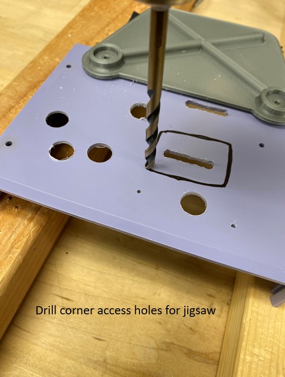
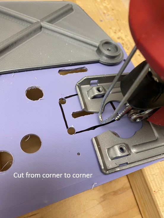
-
Insert jigsaw through a hole, check blade clearance to the bench, and then cut gently but firmly along your line, holding the plastic box steady so it can't move.
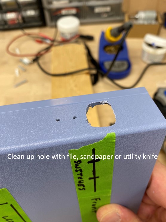
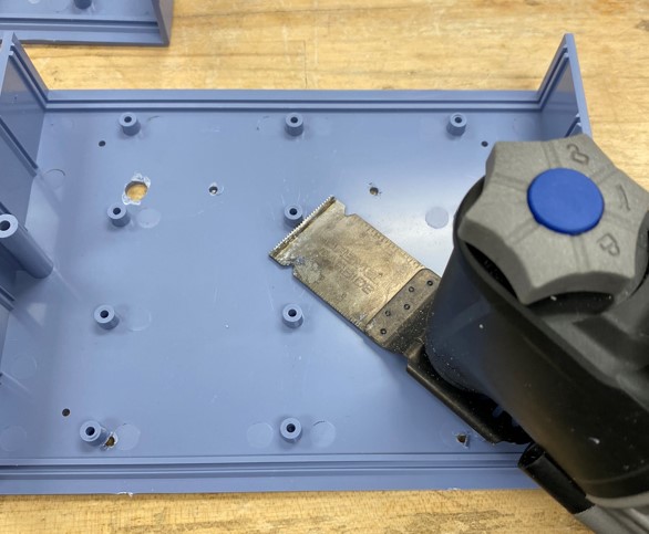
Example: Making a Hole of Arbitrary Shape with the Oscillating Saw
To saw a hole of arbitrary shape into your box with the oscillating saw, the following procedure is recommended:
- Draw the outline of your cut on the box.
- Obtain scrap wood that can lift the plastic high enough above the bench that the oscillating blade will not hit the bench.
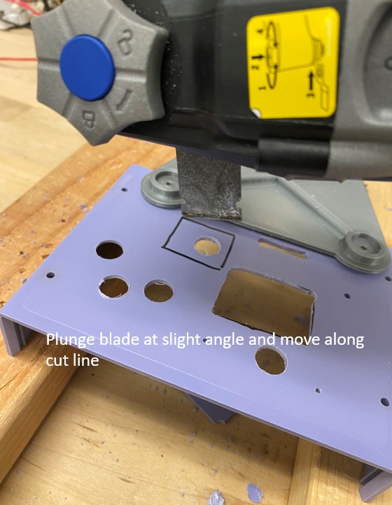
-
Plunge the blade of the oscillating saw into the cut at a slight angle, rather than going through square. This helps the blade evacuate chips from the cut.
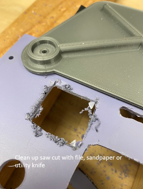
-
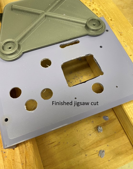
Clean up grunge around cut with a file or sandpaper or by carefully scraping with a utility knife. ("Grunge" is all the mangled bits of plastic left after you use the saw.)
Example: Making a Hole of Arbitrary Shape with the Dremel
To mill a hole of arbitrary shape into your box with the Dremel rotary tool, the following procedure is recommended:
- Draw the outline of your cut on the box.
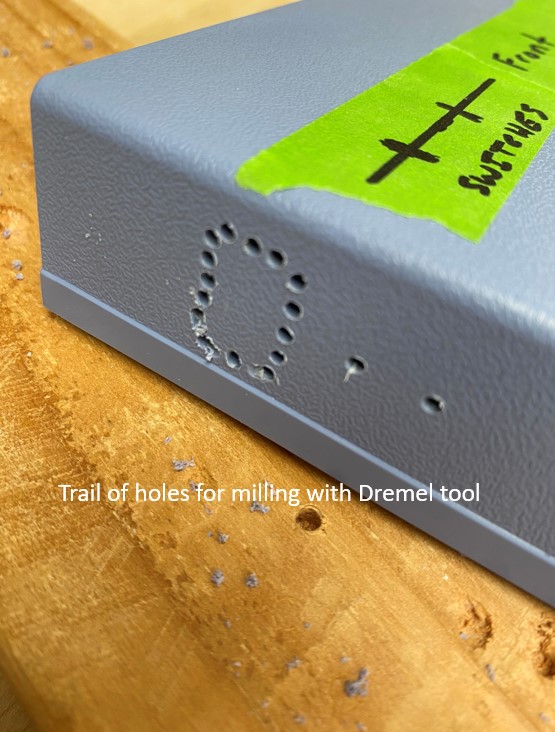
-
Drill a path of holes along your cut. This reduces the amount of work the Dremel tool has to do.
-
To initially plunge into the material, hold the Dremel at a bit of an angle and turn the speed to high. Make sure the box is held steady, with a clamp or vise if necessary.
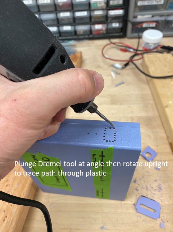
-
Once the Dremel is through, tilt it perpendicular to the surface and carve your way around the path of holes you drilled earlier.
Don’t use the Dremel later on in construction when all your components are in, as it makes very fine dust that is bad for electronics.
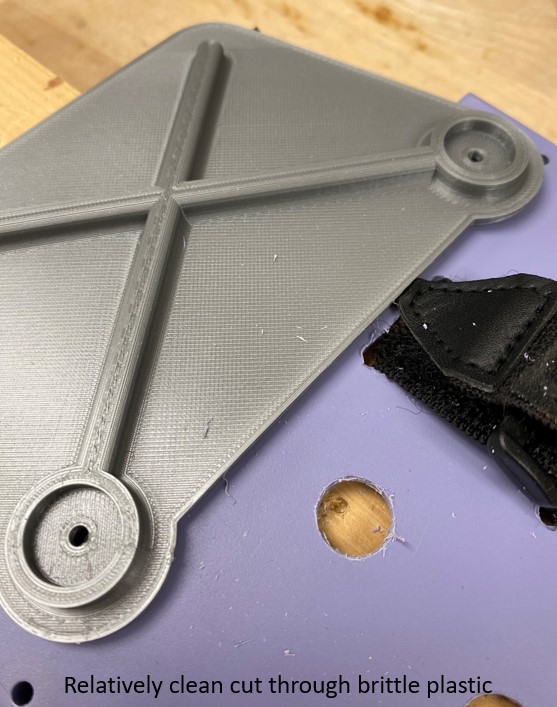
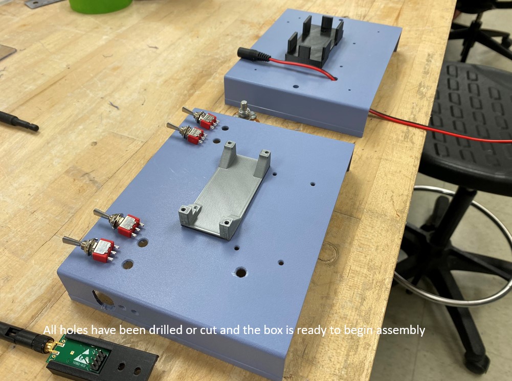
What Your Box Should Look Like After Creating Holes
With a bit of careful work, your box should now look something like this:
Tip for Success
As you will be working on this box for several lab sessions, it may be tempting to close it up with the provided screws between labs. Unfortunately, the plastic is brittle and the screws are very easy to strip with the screwdriver. This means that the more times you screw the box shut, the more chances you have of having the screws threads strip the plastic and no longer hold, or of stripping the phillips socket of the screw head and not being able to get the screws back out.
It is a good idea to just tape the box shut from the outside with masking tape between labs, and then at the end when you are sure the box works properly, to only screw it shut once.
3. Begin Installing Components: Switches, Buttons and Potentiometers
The reason to begin with these basic components is that installing the fragile electronics later makes it less likely that they will get damaged by tools and solder. You are going to be using some combination of toggle switches, push buttons and potentiometers. You can solder the wire leads on them either in the box or out of the box. The choice depends on what is more convenient to you.
The demonstration box in this manual will have 4 toggle switches for fore-aft control of the 4 thrusters and one potentiometer for control of a servo motor. If you use buttons, you will need two buttons per thruster; one button for forward and one for reverse. Both the toggle switches and the buttons are “momentary on” devices, meaning they pop back to an open circuit when you release them, rather than remaining latched on when you activate them.
How Toggle Switches Are Connected
The way the toggle switch works is that the middle electrical terminal is common to both circuits in the switch, and the two outer terminals are connected by pushing the switch one way or the other. If you push the switch up, it actually closes the circuit with the opposite electrical terminal on the back of the switch, as shown below:
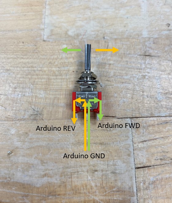
FWD (forward) and REV (reverse) are shown as an example; the switch itself is not directional. GND means “ground”, as in the “ground” in the electrical circuit.
How Push Buttons Are Connected
The way the push button works is that the circuit between the electrical terminals on the back of the button is only closed when the button is pushed down, as shown below.
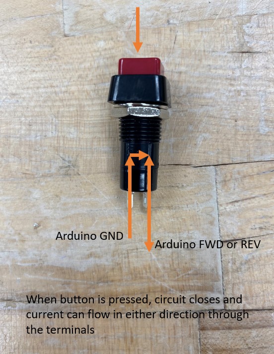
Like the switch, the button is not directional. FWD and REV and GND are shown for examples.
Best Practices: Color Conventions in Wiring
Now is a good time to talk about best practices when it comes to wiring your switches. First, you should know color conventions for positive and negative wires.
-
If a schematic calls a wire
POS,+, orVIN, that wire should be RED. -
If a schematic calls a wire
NEG,-, orground, that wire should be BLACK.
In your house / apartment / dorm room, the ground wire is bare copper or GREEN. You can depart from this convention, but be aware that it will probably confuse other people who are looking at your circuit.
Worst Practices: How NOT to Solder Your Switches/Buttons
When wiring your switches you also need to follow good practices for stripping, bending, and soldering your leads. You will be using 22 gauge, solid core wire when wiring your switches. In simple terms, this is a skinny little single wire in a colored insulating jacket. This is in contrast to stranded wire, which you will encounter in a little bit.
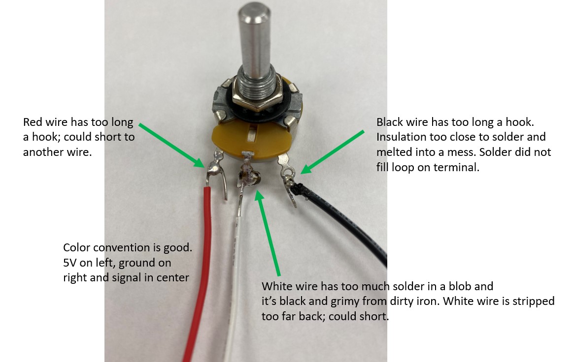
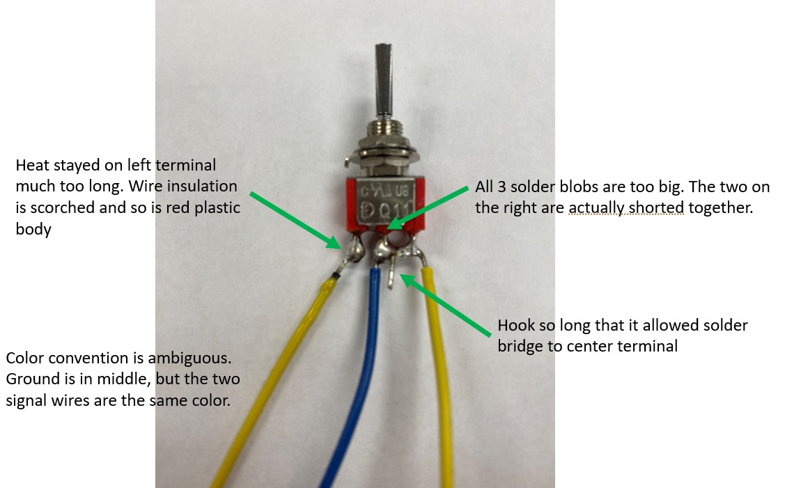
Soldering well takes time and patience. If you don’t solder your leads well, your controller will not work and you can damage our equipment. It is helpful to know what not to do when soldering, so see the pictures below for how your wiring should NOT look.
Best Practices: Properly Soldering Your Switches/Buttons
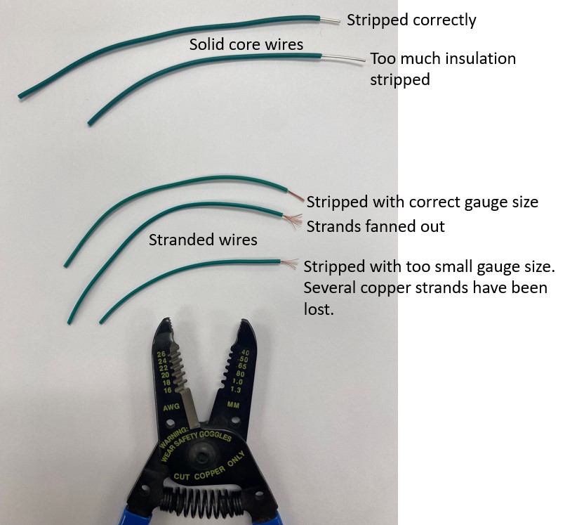
When you strip the insulation off of wires, there are a few things you need to know. Wires are labeled with a gauge size. Without going into the history of this system, the basic principle is that larger gauge numbers mean smaller wire and vice versa. You will be using a lot of 22 gauge wire in this class, which is quite a small size.
When you use the wire stripper, you need to match the wire gauge to the notch in the stripping tool. If you use too large a notch, you won’t get the insulation to come off cleanly, and if you use too small a notch, you can cut the wire, or in the case of stranded conductors, accidentally remove a bunch of the fine strands of wire.
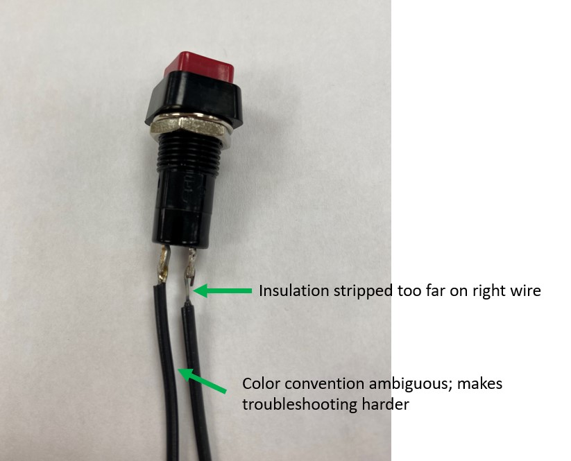
The other nuance in stripping wire is to strip the right amount of insulation. You do NOT want a bunch of exposed wire in your box because that is a sure way to get shorted wires, which means that two wires touch and create an undesired electrical path. If you strip too little, you might not have enough wire inserted into a terminal block, and the wire could fall out. So pay attention and be meticulous with your wire stripping. We are not telling you exactly how much wire to strip, because it will vary, so always strip as little as you reasonably can. The picture below gives some examples of correct and incorrect amounts of wire stripping:
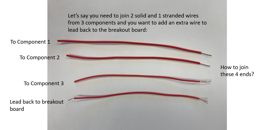
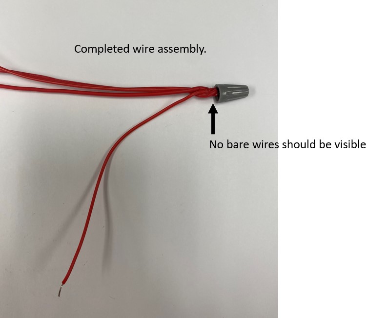
Each toggle switch will need a ground wire soldered to its center terminal and two signal wires on the outer terminals. Each button will need a ground wire soldered to one terminal or the other, it doesn’t matter which. The other terminal on the button will get a signal wire. The potentiometer will need a ground wire on one outer terminal, a 5V wire on the opposite outer terminal, and a signal wire to the center terminal. Strip your wires properly and form a small hook on the end with needle-nose pliers. The wire hook will be put through the holes in the terminals and then squished closed with needle nose pliers to hold it tightly to the terminal for soldering.
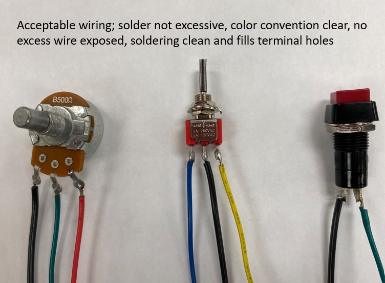
What Your Controller Should Look Like After Soldering Switches/Boxes
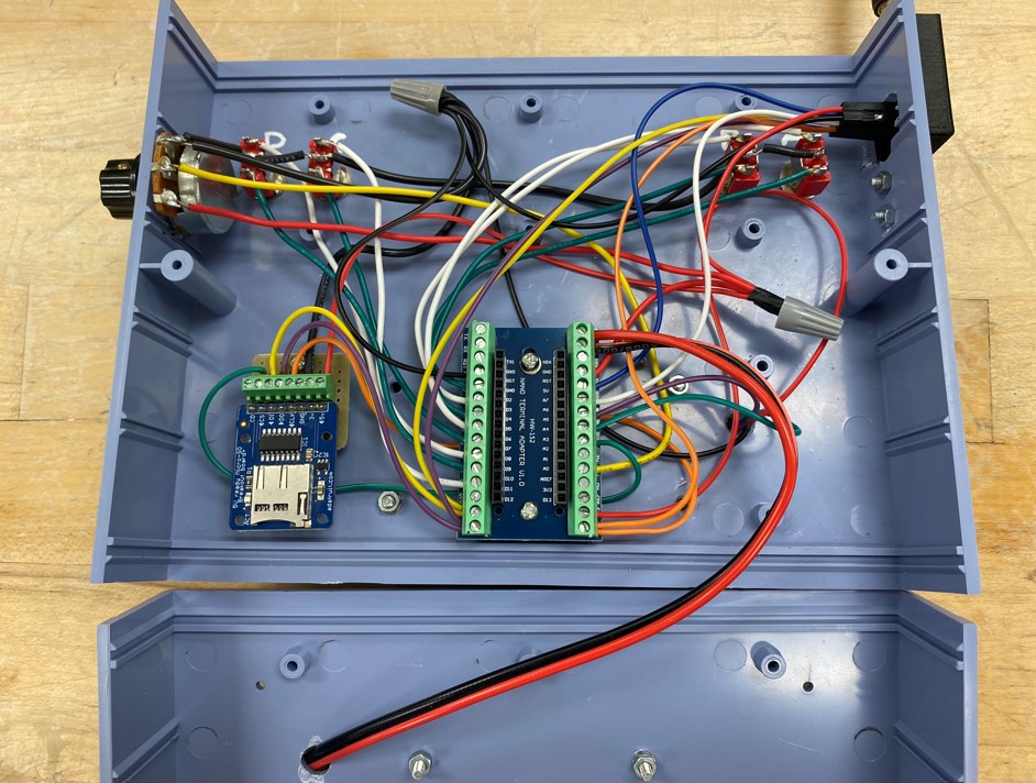
Once you have soldered all the wires to your switches, buttons and potentiometers, your box will look something like the picture below.
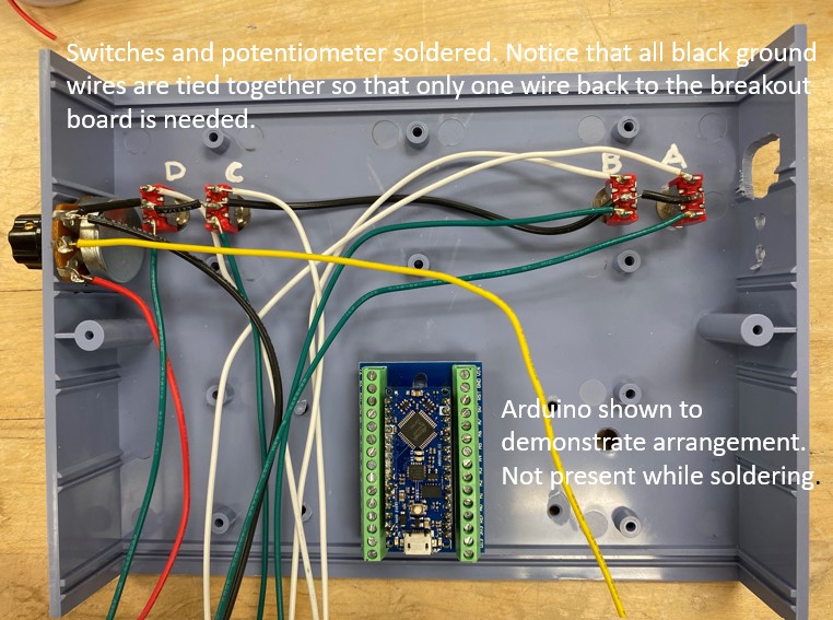
There are a few things to note. You will notice that the box in the figure above has all the ground wires for the potentiometer and switches tied together, with one spare lead left to go to a ground pin on the Arduino. This is because it is very difficult to get more than one wire into the terminals on the Arduino breakout boards. It is better to tie together any multi-wire assemblies and leave an extra lead sticking out to make a single connection to the board.
In the picture above you will also notice that I have temporarily placed the Arduino and breakout board so that you can see the sides the wires ultimately need to be on, and you will notice that I have left enough extra wire length to easily get from the switch/button to the Arduino board and breakout board. It is bad practice to splice together wires to make them longer if you cut them too short. The more connections you have, even if they are good connections, the more opportunities you have for breakage and other failures.
Finally, you will notice that all the switches in the box below are on the front face of the box. This makes wiring the box easy, but many of you will choose to have buttons or switches on the back face. This means while wiring, you will be working with the two halves of the box at once, laid out like an open clam shell. You will need to think about how to leave enough wire slack and also about how best to run the wires so that when you close the box, it will not pinch them or be a huge mess.
Tip for Success
Use the different colors of wire to your advantage. If you choose to use only white wires for everything, for example, when it comes time to make all your connections or troubleshoot a problem, it will be very difficult to follow the wiring and figure out what goes where. The choice of color scheme is up to you, but think it through and do it logically.
4. Continue Installing Components: Breakout Board, Antenna, SD Board, LCD Display
Once you have your switches and buttons wired, it is time to move on from the basic electrical components to the more delicate electronic components.
Mounting the Breakout Board for the Arduino
Start by placing the breakout board for the Arduino and the SD card board. Your choice of placement should be influenced by how your team decides to mount the breakout board. You have two options: use the mounts that came with the box, or make your own!
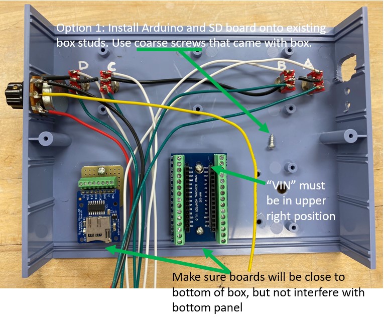
Option 1: Use the Screws and Mounting Points In the Controller’s Box
Option 1 is to screw the Arduino breakout board and SD card board to the existing box studs using the coarse-thread screws that came with the box kit. Make sure that the components are close to the edge of the box and oriented the correct direction so that you can actually access them once the box is closed.
Tip for Success
When you are working with electronics, don’t over tighten fasteners. You are not attaching wheels on a car using lug-nuts on here… tighten the screws and nuts just till snug. It is very easy to crack circuit boards and components if you over tighten fasteners.
Option 2: Put Things Wherever You Want… But Mounting Is Trickier
Option 2 is to position the Arduino breakout board and SD card holder in some other place. In this case, some of the molded plastic studs in the box might be in your way. Use the oscillating saw like a lawn mower to cut away studs that are in your way.
Since you will not be using the included coarse-threaded screws now, you need to use the provided M3 fine-thread machine screws to thru-bolt your components to the box. This means that the machine screw will go all the way through your box and be fastened with a washer and nut. You need to use the 3D printed spacers for the breakout board and SD card board to raise them up off the surface of the plastic box. If you don’t, when you tighten the screws, the boards can flex toward the box and crack, causing destruction of the component.
![]()
Tip for Success
Remember! When you are working with electronics, don’t over tighten fasteners. Tighten the screws and nuts just till snug. It is very easy to crack circuit boards and components if you over tighten fasteners.
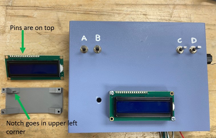
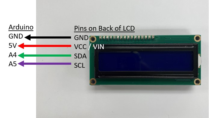
Mounting the LCD Display
Next install your LCD display screen on the front of your controller. The notch in the 3D printed holder should be to the top-left side. You can use 2 machine screws placed diagonally to secure the screen. You can use 4, but it is not strictly necessary. Remember to use washers under screw heads and under nuts.
Tip for Success
Always use the shortest fasteners that will do the job. You don’t want excess machine screw sticking into your controller as it can get in the way, chafe wires, and even short out circuit boards, if it presses against them.
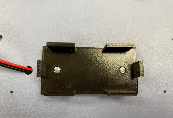
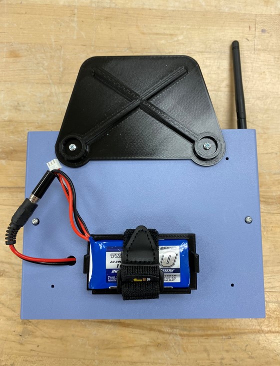
Mounting the 3D Battery Holder
Next install the 3D printed battery holder onto your controller, as shown below.
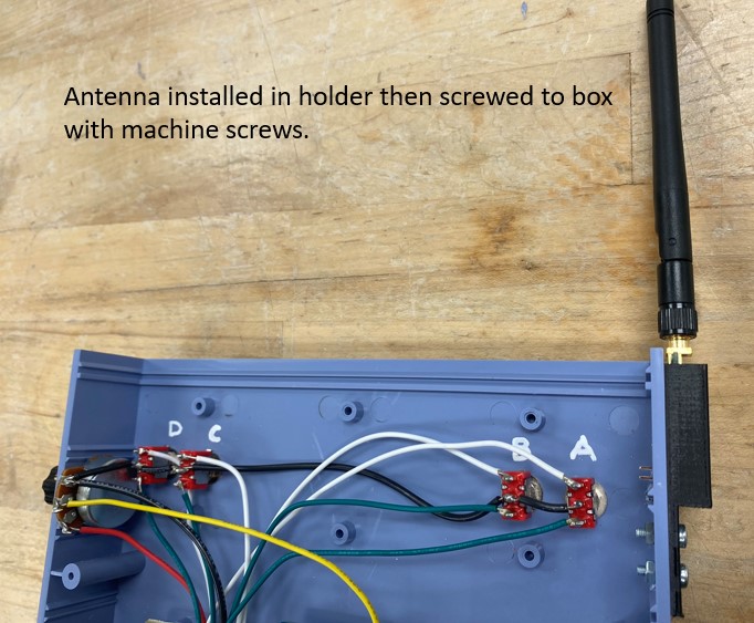
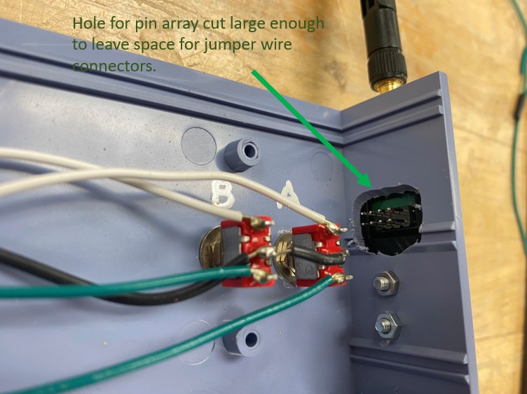
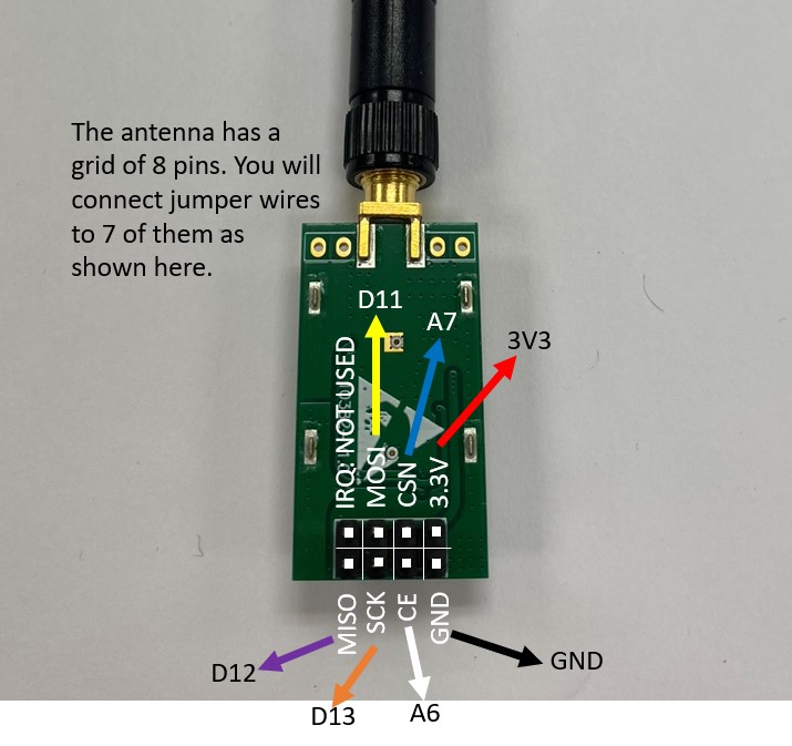
Mounting the Antenna
Next install the antenna in the 3D printed antenna holder. You should have cut a rectangular hole in your box big enough to leave some space around the antenna connection pins.
5. Making Wired Connections Between Components
Now that all your major components are installed in your controller, it is time to wire them together. The pictures below show how to connect the components.

When you have made all your electrical connections, your box should look something like the picture below.
There are a few important details to notice about the box in the picture above:
-
Tidiness. Your wiring should be tidy. You should have enough slack that the wires aren’t pulled tight against their terminals, but there shouldn’t be a lot of excess wire crowding the box. The wires should be led in smooth arcs in reasonable paths to their destinations rather than kinked or tangled like spaghetti.
-
No exposed wire. You should see very little or no bare metal beyond the open ends of the switch and button terminals. Where the wires enter screw-terminals, they should be stripped no more than necessary to make a solid entry into the terminal.
-
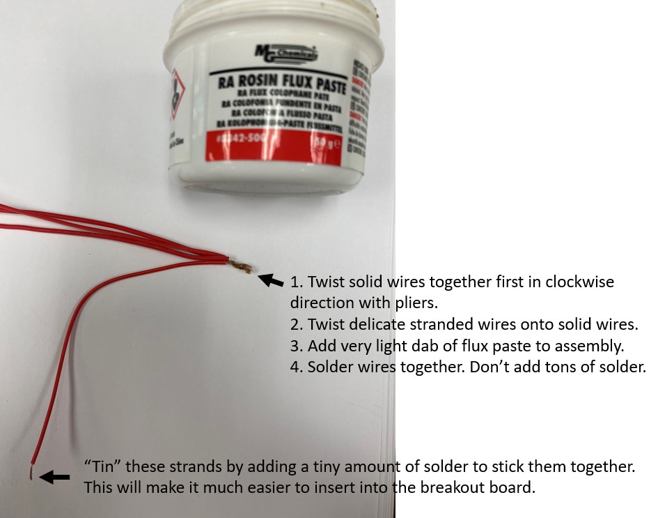
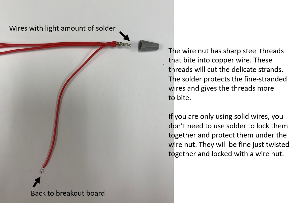
Dupont wire best practices. Dupont wires, or the jumper wires with the plastic ends, are a very convenient way to make electrical connections. They do create a possibility of loose connections however, particularly when the plastic ends get tugged. So you can see in the picture above that anywhere Dupont jumpers were used, like on the antenna, the other end was cut, stripped and lightly tinned with solder before being inserted into the screw-terminals. Tinning stranded wires makes them much easier to insert into the terminal and to get a tight connection in the terminal.
-
Screw terminals. There is just barely enough room in any screw terminal to get one or two small wires into them. That is the reason you can see all the 5V red wires and black ground wires bundled together with only one wire going back to the screw-terminal. Don’t over tighten the screws on the terminals. Tighten enough that your wire is snug when you give it a light tug and it doesn’t fall out. Be sure to not get the wire insulation in the screw terminal; you only want the copper wire in there.
-
Wire color. You have access to a variety of wire colors. The wire colors I have chosen are not special, with the exception of the red and black wire conventions. Use the colors to your advantage to make your wiring as easy to understand as possible.
6. CHECKPOINT
STOP!
Your box must be checked by Justin or an IA before you will be given an Arduino.
We require this checkpoint because in the past, due to faulty wiring, many components have been destroyed by students. You are expected to have followed this guide carefully and done a tidy job of wiring your box. Putting the Arduino in the breakout board and powering it up is when major errors become immediately evident when the Arduino starts smoking and is destroyed. We need to avoid destroying equipment when a reasonable checklist will help us catch most errors in wiring the controller.
Before you are given an Arduino and a battery to power up your box, we will check it with the controller-engineers who built it. You will be expected to point out each connection as we check it. If you have done a tidy job, this will be a quick process. If your box is a mess, you can expect a lot of rework.
Controller checkpoint list:
Tip for Success
When poking around inside an electrical device, never use a metal object like a screwdriver, even though it is convenient. Use something plastic, like a pen with the cap on, to point at things or push wires to the side when inspecting a live circuit.
If you need to move a wire, or tighten something with a screwdriver, unplug the device first. Even with low voltage devices like the controller, you can short components out with a metal probe and destroy them.
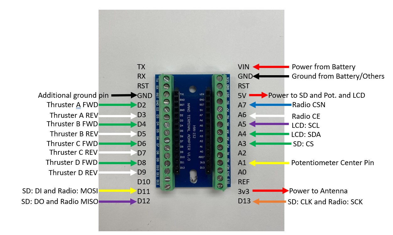
Once you have proven that you have done a correct job of wiring your controller, you will be given an Arduino to plug into the breakout board, which should be installed as shown below:
7. Cutting Box Endcaps and Final Testing
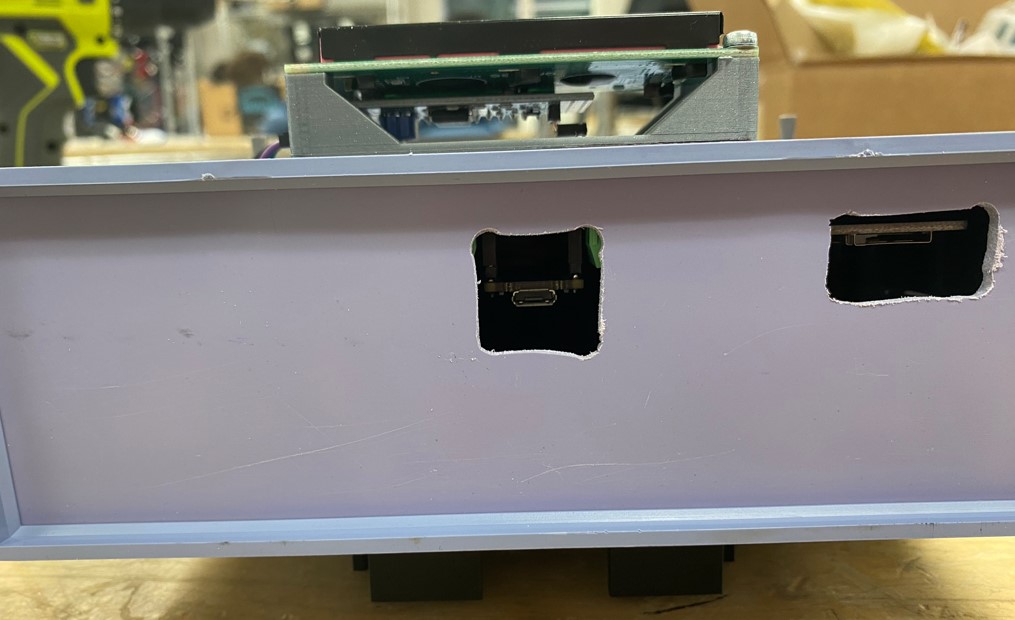
Depending on where you installed your components, you will likely need to cut access holes for the SD board and the Arduino USB port at this point. See the picture below for an example.
Once your box is complete, but before screwing it together, it is time to power it up with your laptop. The Arduino can be powered both by the 5V power coming from your computer’s USB port, or from the 7.4V battery pack that you will use for remote operations.
-
Download the Arduino IDE onto your laptop.
https://www.arduino.cc/en/software - Download the "starter code" for the ROV controllers. Open this code that you will load onto the Arduino board.
-
Connect the USB from your computer to the Arduino to power up the Arduino. The Arduino lights should come on and the LCD screen should say "System Ready" within about 2 seconds.
If the screen shows weird characters or does not light up or there is any smoke, unplug your Arduino from the USB cable instantly and get Justin or an IA to help.
-
Upload the code from your computer to the Arduino. You have to only update one line of code if you are using a standard controller. Where the code says:
const uint8_t payloadNumber = #;
You will need to change the default number `#` to the number of the payload you are currently using. This will be the case every time you get a different payload, and you will not get the same payload each time, which is why your Arduino USB port has to be easily accessible. From the dropdown box, you need to select "Arduino Nano Every" and whatever port the USB is plugged into on your computer. Next click the right arrow to upload the code. The screen will say compiling and then uploading and then upload complete.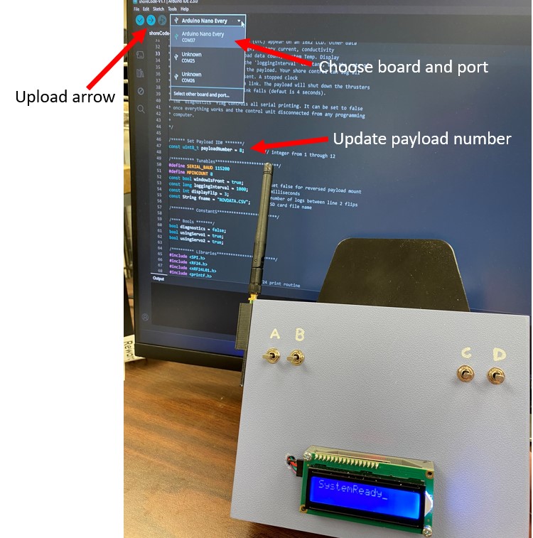
Test your controller while it is plugged into your computer. Justin or the IA will help you set up a test payload to make sure your controller works. Your controller should be showing data readouts from the payload. 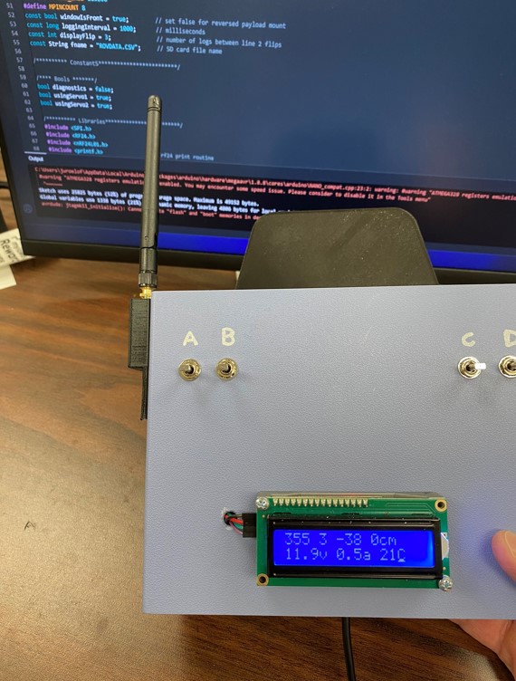
Operate your switches and buttons. If they are working, you will see LEDs in the payload tube come on, green for FWD and red for REV.
If your controller works, you should now screw it shut and get a velcro battery strap for the battery holder. Disconnect from your computer and connect to a battery and verify that your controller still works.
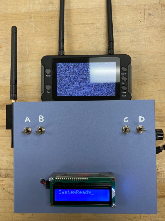
Once your box is closed, get a piece of velcro for attaching the video monitor to the controller. This monitor will be connected to the camera on the payload and will allow you a first person point of view from your ROV. You will need to stick the fuzzy side velcro to your 3D printed video monitor bracket, unless the velcro is already on there from a previous class.
At this point, your controller is complete and ready to operate your ROV. Congratulations!